
When does liquid cooling make sense for industrial electronics?
DETAILS
Liquid cooling makes sense for industrial electronics when the thermal problem is no longer local, temporary, or solvable by improving airflow. The strongest justification appears when heat sources are concentrated in a small enclosure, inlet air is already hot or contaminated, acoustic limits restrict fan capacity, or a required operating life leaves little margin for elevated semiconductor and capacitor temperatures.
The decision should begin with the complete heat path rather than device power alone. A drive controller, edge-computing enclosure, RF power stage, battery interface, machine-vision processor, or power-conversion cabinet may dissipate a manageable total load while still containing one component whose junction-to-ambient path is inadequate. Conversely, a high total load can remain practical with forced air when it is distributed across a large, clean enclosure with a stable inlet temperature. Liquid cooling is justified by the combination of heat concentration, environmental limits, permitted temperature rise, and reliability target.
Air cooling reaches a practical limit before it reaches a theoretical limit
Fans and finned heat sinks can remove substantial heat, but their performance depends on the temperature difference between the heat sink and the incoming air. As ambient temperature rises, that driving temperature difference shrinks. In a factory enclosure near process equipment, the air entering a cabinet may already be warmer than the room measurement suggests. Air recirculation inside a poorly divided cabinet raises the local inlet temperature further, even when the external fan rating appears sufficient.
Dust, oil mist, textile fibers, conductive debris, and humidity complicate the picture. A fin stack that performs well during an open-bench trial can lose capacity after contamination changes the effective airflow area. High fan speed may delay the problem, but it also increases bearing wear, noise, vibration, and power consumption. Filters protect internal electronics, yet a loaded filter adds pressure drop and makes fan performance highly dependent on maintenance discipline.
Liquid cooling decouples the primary heat-removal path from the quality and temperature of enclosure air. It does not eliminate the need to manage air around secondary components such as magnetics, electrolytic capacitors, relays, connectors, and control boards. It does, however, allow high-flux devices to transfer heat to a controlled loop rather than relying on increasingly aggressive internal airflow.
Power density is more useful than total power
A cabinet-level heat number is a starting point, not a selection criterion. Two assemblies that each reject the same amount of heat can demand entirely different cooling architectures. One may spread loss across a large aluminum chassis; the other may concentrate it beneath power modules, CPUs, GPUs, laser drivers, or RF transistors. The latter creates a steep temperature gradient through the package, interface material, cold plate, and coolant channel.
Assess heat at three levels:
- Device level: junction temperature margin, allowable case temperature, transient load profile, and the resistance from junction to the mounting surface.
- Assembly level: spacing between sources, heat spreading through baseplates or PCBs, airflow shadowing, and whether adjacent components are heated by the same plume.
- Enclosure level: external ambient conditions, cabinet sealing, available surface area, ventilation route, and whether waste heat can be discharged outside the working area.
A common misread occurs when a thermal model reports acceptable average cabinet temperature while a small number of devices repeatedly approach their thermal limit. Average air temperature does not reveal hotspot severity. Infrared inspection can also mislead when surfaces have different emissivity or are viewed through a window. Temperature sensors placed at the coolant outlet or enclosure exhaust provide useful system information, but neither substitutes for measurement near the critical device case or a validated junction-temperature estimate.
Conditions that often justify a liquid loop
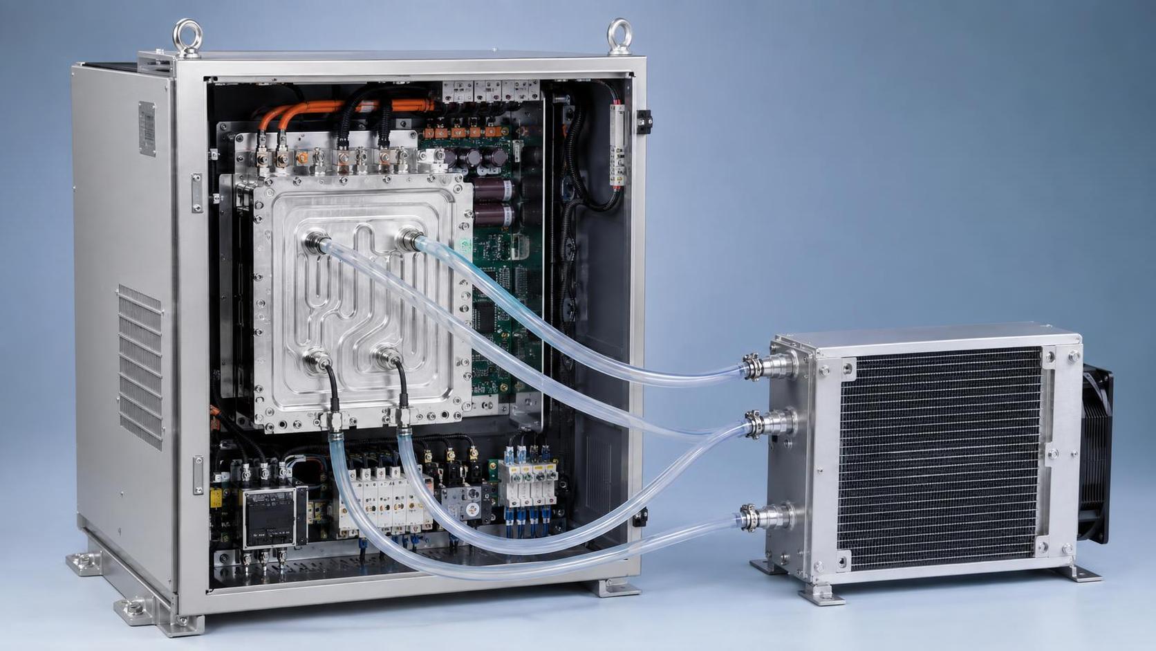
Liquid cooling becomes a strong option when the equipment must remain compact despite high losses. This often occurs where cabinet dimensions are fixed by machinery, rack spacing, mobile equipment, or existing cutouts. Expanding a heat sink or adding larger fans may be physically impossible, while a cold plate can move heat through hoses to a remote heat exchanger or facility-water interface.
High ambient conditions create a second clear use case. Air cooling becomes progressively less forgiving when equipment is located beside furnaces, outdoor process lines, solar-exposed enclosures, engine compartments, or areas with poor ventilation. A liquid loop connected to a suitably located heat exchanger may use a more favorable heat-rejection location. The benefit comes from relocating the final heat exchange, not from treating liquid as inherently cold.
Sealed or near-sealed enclosures are another important case. Sealing may be required to limit ingress of dust, washdown moisture, corrosive gases, or conductive particles. Once outside air cannot be freely circulated through the cabinet, the enclosure wall becomes part of the thermal design. A liquid-to-air heat exchanger, liquid-to-liquid plate exchanger, or externally mounted cooler can remove heat without exposing internal electronics to the plant atmosphere.
Short-duration peaks deserve separate treatment. A process controller may operate at modest average power but experience repeated bursts that force local semiconductor temperatures to cycle sharply. Liquid cooling can reduce the peak temperature and improve the thermal time constant near the source. Yet a loop sized only around average heat rejection may still fail during bursts if coolant volume, flow rate, cold-plate mass, or heat-exchanger response is inadequate. Transient thermal behavior must be modeled or tested rather than inferred from steady-state ratings.
Thermal cycling can be the deciding issue
Many industrial failures are driven less by the highest recorded temperature than by repeated expansion and contraction. Power semiconductors, solder joints, thermal interface materials, ceramic substrates, copper planes, and mechanical fasteners do not expand at the same rate. Repeated temperature swings can fatigue interfaces even when the peak temperature remains below a published limit.
A well-designed liquid system can narrow the temperature excursion at a power module or processor package. That is valuable where load cycling is frequent and service access is difficult. It can also introduce a new form of cycling if coolant control is unstable. Rapid changes in coolant supply temperature may produce thermal gradients across a cold plate, especially where channels are unevenly distributed or one inlet feeds a dense cluster of devices before reaching less demanding areas.
Coolant temperature should therefore be controlled for stability as well as for absolute value. A colder supply is not always better. If the coolant falls below the dew point of the surrounding air, condensation can form on hoses, fittings, cold plates, or nearby conductive surfaces. In humid environments, the design needs an explicit condensation strategy: insulated lines, controlled coolant setpoints, vapor barriers where appropriate, leak detection, and a layout that prevents any accidental moisture path from reaching energized circuitry.
The loop architecture must match the maintenance reality
Liquid cooling changes the maintenance burden; it does not remove it. A self-contained loop may contain a pump, reservoir, heat exchanger, fan assembly, fittings, hoses, coolant, sensors, and controls. Facility-water cooling removes some equipment from the cabinet but adds concerns about water quality, pressure variation, isolation, and site plumbing availability. The best architecture is the one whose failure modes and service tasks fit the installation, not the one with the highest nominal thermal capacity.
Pump selection deserves attention beyond flow rating. Flow resistance changes with hose length, quick-disconnects, narrow channels, filters, bends, and parallel cold plates. A pump that meets a nominal flow number may operate far from that point after the actual pressure-drop curve is assembled. Cavitation risk, pump orientation, startup behavior, electrical noise, and the consequences of a stalled rotor should be addressed early.
Coolant choice also affects more than freezing point. Water-based mixtures offer favorable heat capacity but need appropriate corrosion control and compatible materials. Mixed-metal loops involving aluminum, copper, brass, stainless steel, nickel coatings, soldered joints, and elastomers require deliberate compatibility review. Corrosion products can obstruct small channels long before a large leak is visible. Some dielectric fluids reduce electrical-conductivity concerns, but their thermal properties, viscosity, seal compatibility, cost, and handling requirements alter the rest of the design.
Cold-plate interfaces determine whether the loop performs as expected
A capable chiller cannot compensate for a poor mechanical interface. The flatness of the mounting surface, fastener torque pattern, thermal interface material thickness, pad compression, and clamping force strongly influence contact resistance. Excessive interface material is often used to mask unevenness, but a thick layer can become the dominant thermal barrier. Too little material can leave voids, particularly where surface finish or coplanarity varies.
Cold plates must also be evaluated for pressure drop and flow distribution, not only thermal resistance. A channel layout that cools the inlet side effectively may leave downstream devices warmer. Parallel branches need sufficient hydraulic balance; otherwise, the lowest-resistance route receives disproportionate flow. In a multi-module system, this can produce an intermittent fault pattern in which one module trips first under a particular load sequence even though all modules use the same hardware.
Mechanical integration matters as much as thermal integration. Hoses require bend radius, strain relief, abrasion protection, and clearance from sharp sheet-metal edges. Quick-disconnect couplings simplify replacement but add pressure drop and potential leak points. Service procedures should define how a module is isolated, drained, refilled, purged, and functionally tested without exposing electronics to spilled coolant. A loop that cannot be reliably purged will retain air pockets, reducing local heat transfer and causing pump noise or unstable flow.
Reliability analysis should compare complete failure paths
Air cooling is often treated as simpler because it has fewer fluid components, but a fan-dependent system still has moving parts, contamination sensitivity, blocked-flow risk, and a potentially rapid temperature rise after fan loss. A liquid loop introduces more components, yet it can provide useful diagnostic signals: flow, pressure, coolant temperature at inlet and outlet, pump speed, and leak status. Those signals only improve reliability when the control system has defined actions for abnormal conditions.
For each cooling architecture, identify the detectable failure, the time available before a critical temperature is reached, and the equipment response. A pump failure may allow a short controlled shutdown if cold-plate mass and coolant volume provide thermal inertia. A hose rupture may require immediate isolation. A fouled heat exchanger often develops gradually and can be detected through an increasing coolant-to-ambient temperature difference. These scenarios should be considered under maximum ambient temperature and realistic load, rather than under a convenient laboratory condition.
Redundancy should be applied selectively. Dual pumps, parallel fans, bypass paths, and dual heat exchangers add parts, control complexity, and validation work. They are warranted where uninterrupted operation and thermal consequences justify them. In other equipment, accurate sensing, conservative derating, and an orderly shutdown path may provide a more robust outcome than redundant hardware with poorly defined maintenance.
Lifecycle cost needs a boundary wider than the cooling hardware
The purchase cost of a liquid-cooling assembly is visible; the cost of enclosure enlargement, acoustic treatment, filter replacement, fan replacement, plant heat rejection, downtime, and field service is often distributed across different budgets. A fair comparison includes installation labor, hose routing, connectors, controls, coolant service, spare parts, and the cost of proving leak integrity during production.
Thermal performance should be compared at the required operating condition, including ambient temperature, altitude where relevant, cabinet configuration, load duty cycle, and allowable component temperatures. Comparing a liquid-loop rating at favorable inlet conditions with an air-cooling rating at a harsher enclosure condition produces a false economic result. The same discipline applies to energy use: pump power, external fan power, facility-water pumping, and any chiller energy belong within the same system boundary.
Liquid cooling is therefore justified when it creates a controllable thermal path that air cannot maintain within the available size, environmental exposure, noise limit, and reliability margin. If airflow can meet those requirements with reasonable service access and acceptable component temperatures, liquid adds unnecessary complexity. When heat density, sealing, ambient conditions, or thermal cycling remove that margin, a properly engineered liquid loop becomes a practical part of the electronics design rather than an exceptional measure.
Recommended News
- Heat DissipationHow to prevent overheating in automotive PCB power distributionPrevent overheating in automotive PCB power distribution with practical tips on copper layout, thermal paths, and testing. Discover how to reduce hotspots and improve reliability.
- Heat DissipationCan heat spreading intelligence identify hot spots in PCB designs?Discover how heat spreading intelligence identifies PCB hot spots before fabrication. Learn to assess thermal models, validate predictions, and choose design changes that improve reliability.
- Heat DissipationWhich heat sink materials suit high-power electronics made in Germany?Heat sink materials Germany: compare aluminum, copper, graphite, and hybrid designs for high-power electronics. Find the right balance of thermal performance, weight, cost, and manufacturability.
- Heat DissipationHow to assess a graphite materials supplier's capability for thermal partsGraphite materials supplier assessment starts with more than machining. Discover how to evaluate thermal performance, purity, precision, cleanliness, traceability, and testing for reliable thermal parts.
- Heat DissipationHow to assess a heat dissipation supplier before placing an orderHeat dissipation supplier assessment guide: verify thermal performance, materials, process control, samples, capacity, and total risk before placing an order.
- Heat DissipationHow automotive PCB material selection affects thermal reliabilityAutomotive PCB material selection shapes thermal reliability. Explore CTE, Tg, moisture resistance, stack-up design, and proven qualification strategies for demanding vehicle electronics.