
How to prevent overheating in automotive PCB power distribution
DETAILS
How to prevent overheating in automotive PCB power distribution
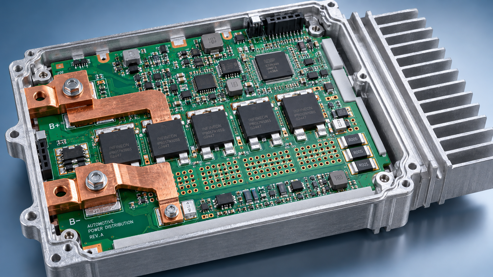
Overheating in automotive PCB power distribution is rarely just a trace-width problem. A board may carry its nominal current successfully on an open bench yet develop a damaging hotspot inside a sealed enclosure. Connector resistance, uneven current sharing, switching losses, and restricted heat flow can all undermine an otherwise reasonable design.
Preventing thermal failure means examining the complete current path under realistic operating conditions. The useful question is not simply, “Can this board carry the rated current?” It is, “Which location reaches its temperature limit first, under which load combination, and with how much margin?” That changes how layouts, materials, protection settings, and supplier evidence should be evaluated.
Define the thermal load before changing the copper
Start with the vehicle operating profile rather than a single current rating. A distribution board feeding pumps, heaters, lighting, or actuators can experience continuous loads, repetitive pulses, motor starting current, and fault conditions. These create different thermal stresses. A short pulse may barely change bulk board temperature while stressing a semiconductor junction or a narrow copper transition.
For each operating mode, establish:
- Continuous and transient branch currents, including simultaneous-load combinations.
- Local ambient temperature, enclosure conditions, mounting orientation, and available airflow.
- Supply-voltage extremes and their effect on load current or switching losses.
- Allowable temperatures for semiconductor junctions, connectors, laminate, capacitors, and interface materials.
- Required operation during faults, shutdown delays, and recovery cycles.
Temperature rise and absolute temperature must remain separate in the assessment. A rise that looks acceptable at room temperature may leave inadequate margin in a hot installation. Likewise, a component’s absolute maximum rating is not an appropriate normal operating target.
Follow resistance through the entire current path
Map the route from the input terminal through protection devices, switches, shunts, copper, vias, and output connectors. Include the return path. An ample supply plane does not compensate for a restricted ground return or a poorly connected terminal pad.
For conductive losses, use P = I2R, with resistance evaluated at operating temperature. As an illustrative calculation, a 1 milliohm connection carrying 40 amperes dissipates 1.6 watts. That is not a universal design limit; it shows why a seemingly small contact resistance can create a concentrated heat source.
Copper resistance increases with temperature, so a room-temperature resistance model can underpredict losses. Connector performance also depends on contact condition, mating quality, mechanical retention, and environmental exposure. Where resistance growth is a credible aging mechanism, include it in the thermal margin rather than assuming new-part performance throughout service life.
Pay particular attention to neck-downs around mounting holes, fuse pads, connector escapes, and layer transitions. These regions may dominate temperature rise even when most of the power plane remains cool.
Use copper geometry deliberately—not just heavier copper
Wider, shorter conductors generally reduce resistance, but nominal copper weight alone does not establish current capacity. Finished thickness, etching tolerances, adjacent heat sources, layer placement, and heat transfer to the surroundings all matter. IPC-2152 provides guidance on conductor current-carrying capacity, but its use still requires attention to the actual board construction and thermal environment.
Expanding copper is often useful where a power path narrows near a terminal. Connecting parallel planes can help distribute current, provided the connections support that sharing. Do not assume that identical-looking layers carry equal current: their resistance and access geometry may differ.
Via arrays need both electrical and manufacturing scrutiny. Finished hole diameter, barrel plating thickness, board thickness, and spacing influence their behavior. Adding vias helps only if current can reach them without passing through another bottleneck. Dense arrays may also complicate fabrication or assembly, especially near soldered power pads.
When the required copper structure becomes impractical, compare alternatives such as busbars, copper inlays, or a separate high-current interconnect. These introduce cost, assembly, insulation, and mechanical considerations, but may be more controllable than forcing excessive current through a constrained multilayer layout.
Separate semiconductor heating from board heating
In electronically switched distribution, MOSFET losses can dominate the local thermal picture. Evaluate on-resistance at the expected junction temperature and actual gate-drive voltage, not only the headline datasheet value. For pulse-width-modulated channels, switching losses also depend on operating frequency, voltage, current, and transition behavior.
Fault handling deserves a separate check. A switch may enter current limiting or linear operation while waiting for protection to act. Low on-resistance does not establish that it can safely survive this interval. Review the device’s safe operating area, transient thermal response, and protection timing against the actual fault waveform.
Package thermal-resistance figures require context. Junction-to-ambient values depend strongly on the reference board and test conditions; they are not fixed properties that transfer unchanged to every enclosure. Use package-specific thermal models and realistic board geometry. Parallel switches also require analysis of current sharing, gate routing, and thermal coupling rather than a simple multiplication of current ratings.
Give heat a defined route out
Copper spreading reduces local temperature gradients, but heat still needs a path to the surroundings. In a sealed module, that path may pass through thermal vias, a board surface, an interface pad, and a metal housing. Every interface adds resistance, and an unintended air gap can undermine the arrangement.
Specify thermal interface material by more than conductivity. Thickness, compression range, electrical insulation, contact area, aging behavior, and mechanical tolerances determine the installed result. A high-conductivity pad used across an excessive gap may perform worse than expected.
Material selection also needs discipline. Laminate glass-transition temperature is not a continuous operating-temperature rating. Review the laminate’s relevant thermal endurance and construction data, alongside electrical insulation and mechanical requirements. Heavy copper can improve heat spreading, but affects fabrication capability, feature geometry, and soldering behavior.
Keep temperature-sensitive components away from persistent hotspots where practical. Electrolytic capacitors, sensing circuits, and connector housings may impose tighter constraints than the power switch itself. Moving heat away from one device is not progress if it transfers the reliability problem to another.
Validate the installed assembly, not an idealized board
Simulation is useful for locating likely bottlenecks and comparing design changes. Its credibility depends on inputs: copper distribution, contact resistance, device losses, interface properties, and enclosure boundary conditions. Where uncertainty is substantial, run sensitivity studies instead of presenting one precise-looking temperature map.
Testing should reproduce the installation closely enough to challenge those assumptions. Use representative harnesses, connectors, fasteners, enclosure parts, and interface compression. A bench supply connected through oversized laboratory leads can conceal losses that appear with the production harness.
A useful validation sequence is:
- Measure voltage drop across individual high-current segments, preferably with four-wire methods where practical.
- Run critical load combinations until temperatures stabilize, while recording ambient conditions and current.
- Use thermal imaging to locate surface hotspots, then verify critical readings with suitable contact measurements.
- Exercise transient loads and protection events using instrumentation fast enough to capture their electrical behavior.
- Repeat relevant measurements after environmental conditioning to identify resistance or thermal-path degradation.
Infrared measurements need emissivity control, particularly on reflective metal. They also cannot directly reveal a buried conductor hotspot or semiconductor junction temperature. Correlate measurements with the thermal model and device-specific estimation methods rather than treating a surface image as complete evidence.
Make supplier evidence comparable
Thermal performance depends on what is manufactured, not merely what appears in the design file. Request finished copper requirements, relevant plating tolerances, laminate identification, power-pad assembly criteria, and the inspection evidence needed to verify them. For exposed-pad packages, solder void location and distribution can matter alongside overall void percentage.
This is where SiliconCore Metrics’ focus on independent benchmarking across PCB fabrication, SMT assembly, components, and thermal packaging becomes relevant. Comparing suppliers requires aligned test conditions and traceable manufacturing parameters. A lower reported temperature is not meaningful if one board was measured in free air and another inside its intended housing.
Keep quality-system evidence separate from performance evidence. ISO 9001 certification concerns a quality management system; it does not prove a particular board’s thermal capability. Similarly, applicable IPC Class 3 requirements support manufacturing quality expectations but do not replace application-specific thermal validation.
Approve against a thermal budget
A defensible automotive PCB power distribution design has a documented loss budget, identified temperature limits, and measured margin under its critical operating conditions. Protection thresholds should reflect the vulnerable parts of the current path, including locations that a remote temperature sensor may detect too slowly.
Before release, confirm which manufacturing tolerances, load assumptions, and aging effects the validation covers. If the hottest location changes substantially when a contact resistance or interface gap varies within its allowed range, the design needs closer review. The next step should target that sensitivity—not simply add copper everywhere.
Recommended News
- Heat DissipationHow to prevent overheating in automotive PCB power distributionPrevent overheating in automotive PCB power distribution with practical tips on copper layout, thermal paths, and testing. Discover how to reduce hotspots and improve reliability.
- Heat DissipationCan heat spreading intelligence identify hot spots in PCB designs?Discover how heat spreading intelligence identifies PCB hot spots before fabrication. Learn to assess thermal models, validate predictions, and choose design changes that improve reliability.
- Heat DissipationWhich heat sink materials suit high-power electronics made in Germany?Heat sink materials Germany: compare aluminum, copper, graphite, and hybrid designs for high-power electronics. Find the right balance of thermal performance, weight, cost, and manufacturability.
- Heat DissipationHow to assess a graphite materials supplier's capability for thermal partsGraphite materials supplier assessment starts with more than machining. Discover how to evaluate thermal performance, purity, precision, cleanliness, traceability, and testing for reliable thermal parts.
- Heat DissipationHow to assess a heat dissipation supplier before placing an orderHeat dissipation supplier assessment guide: verify thermal performance, materials, process control, samples, capacity, and total risk before placing an order.
- Heat DissipationHow automotive PCB material selection affects thermal reliabilityAutomotive PCB material selection shapes thermal reliability. Explore CTE, Tg, moisture resistance, stack-up design, and proven qualification strategies for demanding vehicle electronics.