
How automotive PCB material selection affects thermal reliability
DETAILS
Thermal reliability in automotive electronics is determined less by a laminate’s headline temperature rating than by how its material system behaves under repeated, constrained temperature change. A board can pass a short high-temperature exposure yet still develop plated-through-hole cracking, copper-to-resin separation, interfacial delamination, solder-joint fatigue, or impedance drift after years of thermal cycling. The decisive issue is the interaction among laminate resin chemistry, glass reinforcement, copper structure, stack-up geometry, assembly profile, and the operating environment.
That is why automotive PCB material selection cannot be reduced to choosing the highest available glass transition temperature (Tg) or thermal conductivity value. Each parameter addresses a different failure mechanism. A technically sound selection starts with the actual thermal load path: where heat is generated, how it leaves the assembly, how far local temperatures rise above ambient, how quickly the board cycles, and which interfaces are forced to absorb strain.
Thermal reliability is an expansion-mismatch problem
Electronic assemblies contain materials that expand at very different rates. Copper expands relatively little in the plane of the board, while epoxy-based laminate expands more. Semiconductor packages, solder alloys, ceramic capacitors, aluminum heat spreaders, and molded housings each introduce further mismatches. When temperature changes, those materials cannot freely move if they are mechanically bonded. The resulting strain accumulates at vulnerable points: solder joints, vias, pad interfaces, copper planes, resin-rich areas, and component terminations.
For a PCB, the coefficient of thermal expansion (CTE) must be considered in two directions. In-plane CTE, generally referred to as X-Y CTE, matters for component-to-board mismatch and for dimensional stability of larger packages. Through-thickness CTE, or Z-axis CTE, is especially important in multilayer boards because plated-through holes and microvias are constrained by copper barrels. Excessive Z-axis expansion during reflow, power cycling, or high-temperature operation can fatigue copper plating and initiate barrel cracks or corner cracking at the knee of a via.
A material may show a manageable Z-axis CTE below Tg but undergo much faster expansion once Tg is exceeded. This change is central to reliability assessment. Tg is not a safe operating boundary, nor is it a point at which a board immediately fails. It is the approximate transition where the cured resin shifts from a relatively rigid, glassy state to a more compliant state and several material properties change significantly. Repeated excursion near or above this region can increase mechanical stress and accelerate degradation, particularly in thick, high-layer-count constructions.
Tg, Td, and T288 answer different questions
Datasheets often list Tg, decomposition temperature (Td), and time-to-delamination measurements such as T260 or T288. Treating them as interchangeable is a common qualification error.
- Tg indicates the resin transition behavior and is relevant to dimensional stability, Z-axis expansion, and mechanical modulus at elevated temperature.
- Td, commonly measured by thermogravimetric analysis, indicates the onset of significant thermal decomposition under the stated test method. It is a material endurance indicator, not a guarantee of assembly survival.
- T260/T288 measure resistance to delamination during exposure at specified temperatures. They can be useful for comparing laminate robustness during severe soldering-related heat exposure, especially where multiple assembly cycles or repair operations are expected.
A high-Tg laminate is generally valuable where the board sees repeated high-temperature exposure, high layer counts, heavy copper, or demanding reflow profiles. Yet high Tg alone does not ensure better reliability. Resin system toughness, moisture resistance, cured-state adhesion, glass weave architecture, and Z-axis expansion all remain relevant. Some high-Tg systems can present processing trade-offs, including different drilling behavior, resin flow characteristics, or adhesion performance if the fabrication process is not aligned with the laminate family.
The meaningful question is not whether a material is “high Tg,” but whether its thermal-mechanical profile remains stable across the board’s actual manufacturing and service envelope. That envelope includes lead-free assembly temperatures, possible double-sided reflow, selective soldering, conformal-coating cure, rework allowances, under-hood soak temperatures, and low-temperature-to-high-temperature cycling.
Thermal conductivity is useful only when the heat path is real
Higher thermal conductivity in a dielectric can reduce local temperature gradients, but it does not replace an effective thermal design. Standard FR-4-class materials have comparatively low through-plane thermal conductivity. Thermally enhanced laminates improve this property through resin formulation and thermally conductive fillers, but the improvement must be evaluated in the context of the entire path from the heat source to ambient.
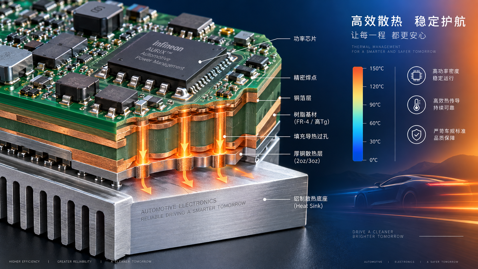
For a power device mounted on the top layer, heat may travel through copper pads, filled and capped thermal vias, internal copper planes, a dielectric layer, an insulated metal substrate, a housing interface material, and eventually a heat sink or enclosure. The thermal resistance of interfaces can dominate the result. A board material with better conductivity may provide little system benefit if via density is inadequate, copper planes are discontinuous, the thermal interface material is poorly controlled, or the enclosure cannot reject heat.
Conductive filler loading can also alter other characteristics that matter in automotive designs: dielectric constant, loss factor, drilling wear, surface roughness response, resin flow, and reliability at copper-resin interfaces. Consequently, the selection of a thermally enhanced substrate should be supported by stack-up-specific thermal modelling and verification, not by a single conductivity value from a datasheet.
Thermal conductivity direction also matters. Many laminate data points describe through-plane performance, while lateral spreading is often governed more strongly by copper distribution. In dense power electronics, a continuous copper plane may spread heat more effectively than a modest increase in dielectric conductivity. In RF or high-speed zones, however, changing dielectric formulation or copper treatment to solve a thermal issue can create an unintended signal-integrity problem. Thermal and electrical requirements must therefore be evaluated on the same stack-up, rather than through separate material decisions.
Moisture changes the thermal risk profile
Moisture absorption is not merely a storage and handling concern. Absorbed moisture can reduce insulation resistance, alter dielectric properties, promote electrochemical migration under bias, and increase vapor pressure during rapid heating. In severe cases, the combination of moisture and reflow stress contributes to internal delamination or “popcorning”-type damage within the laminate structure.
Automotive exposure can include humidity, condensation, salt contamination, fluid vapors, and thermal transitions that repeatedly drive moisture into and out of the board. The relevant material property is not simply a low nominal moisture absorption value. It is the combined behavior of the cured resin, glass-resin interface, copper adhesion system, board edge sealing, coating strategy, and contamination control under the intended environment.
For assemblies exposed to humidity and electrical bias, conductive anodic filament growth is a separate concern. CAF can develop along interfaces in the glass-reinforced laminate when moisture, ionic contamination, electric field, and susceptible material structure coincide. Fine-pitch BGA escapes, high-voltage nodes, close via spacing, and certain glass-weave geometries can make this risk more consequential. A material qualification plan should therefore connect humidity-bias testing and CAF resistance to the layout’s actual voltage gradients and via geometry.
Layer count and copper balance alter the material requirement
The same laminate can perform differently in a simple two-layer controller board and in a thick multilayer domain controller. As layer count increases, the board becomes more constrained, copper distribution becomes less uniform, and Z-axis movement is more difficult to accommodate. Heavy copper sections beside resin-rich areas create uneven thermal mass and localized stress during lamination, reflow, and operation.
Copper balance is especially important. Uneven plane coverage can contribute to warpage, which affects assembly coplanarity and solder-joint quality. Warpage is not solely a laminate issue; it emerges from the interaction of prepreg flow, copper pattern density, glass style, core selection, and the symmetry of the stack-up. Still, material selection determines how much resin is available to fill copper features, how the cured construction responds to temperature, and how consistently the fabricator can maintain final thickness and registration.
High-current designs add another constraint. Internal copper planes may carry substantial current and act as heat spreaders, but they can also raise local temperature and create steep gradients around narrow neck-downs, via fields, or component pads. A substrate should be evaluated with the expected copper weights and feature geometry, not only as a nominal laminate coupon.
Dielectric stability can become a thermal-reliability requirement
In radar, high-speed networking, camera links, battery-management communication, and other frequency-sensitive circuits, temperature changes affect more than mechanical durability. Dielectric constant (Dk) and dissipation factor (Df) can shift with temperature, frequency, resin content, and moisture. These shifts can change impedance, insertion loss, timing margin, antenna behavior, or filter response.
A thermal material upgrade may therefore introduce an electrical trade-off. Different resin chemistry, filler systems, and glass constructions can change Dk consistency and resin content variation. Glass weave can also produce local dielectric inhomogeneity, which becomes significant when traces are tightly coupled or operate at high frequency. Where thermal and high-frequency demands coexist, it is insufficient to specify a general “low-loss, high-Tg” grade. The evaluation needs Dk and Df information at relevant frequencies and temperatures, plus a stack-up that identifies glass styles, resin contents, copper foil type, and impedance tolerances.
Thermal cycling can also affect electrical performance indirectly through microcracks, interface degradation, or moisture ingress. A board may retain continuity while its high-frequency margin has deteriorated. Continuity testing alone is not an adequate reliability screen for circuits with narrow impedance or loss budgets.
Assembly compatibility must be verified with the fabricator’s process
Material data are generated under defined test methods, but production reliability depends on fabrication and assembly conditions. Drill quality, desmear effectiveness, hole-wall preparation, electroless copper deposition, plating distribution, and cure control all influence whether a selected laminate delivers its expected performance. A robust resin system can still produce weak vias if the drilling and plating process is poorly matched to the construction.
For multilayer boards, the material specification should identify more than a generic laminate family. It should control, where relevant, the approved material designation, core and prepreg constructions, glass styles, resin content ranges, copper foil type, final dielectric thickness, and any special requirements for filled vias or sequential lamination. A substitution that appears equivalent on Tg and Td may differ materially in resin flow, Dk, CTE, or moisture behavior.
Lead-free soldering makes this discipline more important because assembly temperatures are materially higher than legacy tin-lead processes. The qualification profile should represent the maximum credible thermal exposure, including repeated reflow where applicable. It should also account for component thermal mass and local heating; a uniform oven profile does not mean every region of a large assembly experiences the same thermal history.
Standards provide a framework, not a complete acceptance decision
IPC-4101 defines performance requirements for rigid and multilayer printed-board base materials and provides a common basis for specifying laminate properties. IPC-6012 and its automotive addendum IPC-6012DA address qualification and performance expectations for rigid printed boards in automotive applications. Test methods are commonly drawn from the IPC-TM-650 series. These documents are useful because they establish terminology, test approaches, and acceptance structure, but they do not substitute for application-specific requirements.
Environmental severity should be derived from the vehicle location and function. ISO 16750 provides environmental conditions and testing guidance for electrical and electronic equipment in road vehicles, including temperature-related environmental considerations. The appropriate test profile depends on whether the assembly is located in a passenger compartment, body zone, engine compartment, transmission area, battery enclosure, or another vehicle-specific environment. OEM and tier-specific specifications may impose additional thermal cycle ranges, dwell times, vibration conditions, humidity-bias requirements, chemical exposure, and traceability controls.
Quality-system certification, including IATF 16949, is relevant to manufacturing governance but does not validate a particular laminate for a particular thermal duty. Likewise, a material recognized in one automotive program should not automatically be assumed suitable for another stack-up, supplier process, or environmental location.
A better qualification question: where will failure initiate?
Material selection becomes more disciplined when it starts from likely failure initiation sites rather than a generic list of desirable properties. For a power module control board, the critical issue may be heat spreading and via reliability beneath a hot package. For a thick controller board, Z-axis expansion and plated-through-hole fatigue may dominate. For a radar board, temperature-dependent dielectric stability and copper profile can be as important as heat removal. For a high-voltage battery-management board, insulation retention, CAF resistance, and moisture behavior may govern the risk.
This approach leads to a more useful evidence package: material data for the relevant construction; thermal modelling of the actual heat path; fabrication capability data; coupon design that represents the most stressed vias and traces; assembly thermal profiles; and environmental testing that combines the relevant stresses rather than treating temperature, humidity, vibration, and electrical bias as isolated events.
The strongest automotive PCB material decision is therefore not the selection of the most extreme datasheet number. It is the selection of a controlled material-and-process system whose CTE behavior, thermal endurance, moisture resistance, dielectric stability, and manufacturability are demonstrably aligned with the board’s location, stack-up, electrical function, and expected thermal cycling history.
Recommended News
- Heat DissipationHow to prevent overheating in automotive PCB power distributionPrevent overheating in automotive PCB power distribution with practical tips on copper layout, thermal paths, and testing. Discover how to reduce hotspots and improve reliability.
- Heat DissipationCan heat spreading intelligence identify hot spots in PCB designs?Discover how heat spreading intelligence identifies PCB hot spots before fabrication. Learn to assess thermal models, validate predictions, and choose design changes that improve reliability.
- Heat DissipationWhich heat sink materials suit high-power electronics made in Germany?Heat sink materials Germany: compare aluminum, copper, graphite, and hybrid designs for high-power electronics. Find the right balance of thermal performance, weight, cost, and manufacturability.
- Heat DissipationHow to assess a graphite materials supplier's capability for thermal partsGraphite materials supplier assessment starts with more than machining. Discover how to evaluate thermal performance, purity, precision, cleanliness, traceability, and testing for reliable thermal parts.
- Heat DissipationHow to assess a heat dissipation supplier before placing an orderHeat dissipation supplier assessment guide: verify thermal performance, materials, process control, samples, capacity, and total risk before placing an order.
- Heat DissipationHow automotive PCB material selection affects thermal reliabilityAutomotive PCB material selection shapes thermal reliability. Explore CTE, Tg, moisture resistance, stack-up design, and proven qualification strategies for demanding vehicle electronics.