
How automotive component compliance testing supports EMC approval
DETAILS
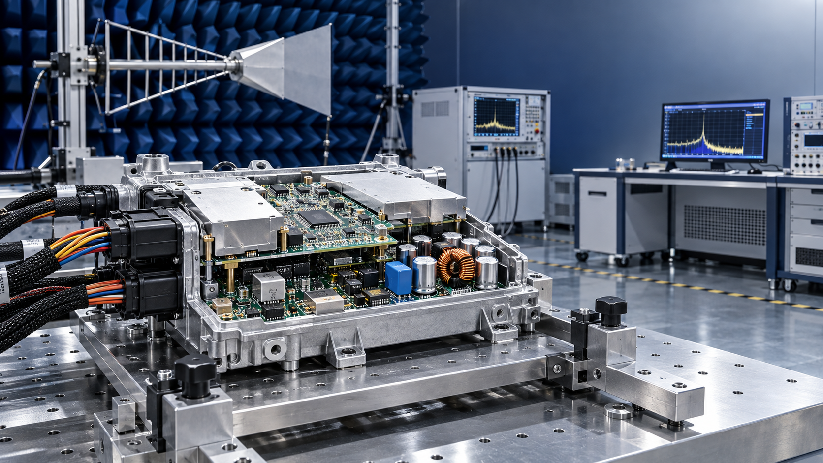
EMC approval is rarely secured by a single successful test at the end of development. In automotive electronics, electromagnetic compatibility depends on a chain of decisions made much earlier: component selection, PCB stack-up, grounding, assembly consistency, enclosure design, cable interfaces, and thermal behavior. Component compliance testing automotive programs support EMC approval by turning those decisions into documented, traceable evidence before a finished module reaches formal validation.
This matters because a component can meet its own datasheet limits and still contribute to an EMC failure once it is installed in a vehicle subsystem. Fast switching devices may create conducted noise through the power network. A passive component with unsuitable high-frequency behavior may weaken a filter. PCB material variation can alter impedance. A soldering defect can change a return path or shielding connection. EMC approval therefore depends not only on whether individual parts work, but on whether their real production characteristics remain controlled inside the intended electrical environment.
EMC approval needs evidence from the component level upward
Automotive EMC evaluation examines two connected questions: whether an electronic unit emits unwanted electromagnetic energy, and whether it continues to operate correctly when exposed to electrical disturbances. The final device is the approval target, but its behavior is shaped by the materials and components inside it.
Component compliance testing does not replace system-level EMC testing. A control unit, sensor module, battery-management assembly, lighting driver, or infotainment board still needs validation in its completed configuration. What component-level work does is reduce uncertainty before that stage. It identifies manufacturing or design conditions that are likely to create emissions, reduce immunity, or make an otherwise compliant design inconsistent across production lots.
The most useful approach is to treat EMC evidence as a hierarchy:
- Material and component data establishes the expected electrical and thermal behavior.
- Assembly inspection verifies that the designed electrical structure was actually built.
- Pre-compliance measurements reveal likely issues before formal laboratory testing.
- Finished-product EMC testing confirms performance in the relevant installation and operating condition.
A gap at the lower levels does not always cause an immediate failure, but it makes the final result harder to predict. It also makes corrective action expensive because the source may be hidden among design choices, purchased components, manufacturing variation, and test configuration.
Which component characteristics have the strongest EMC effect?
Not every part requires the same depth of assessment. Testing effort should follow the electrical risk of the function, the severity of the operating environment, the consequence of failure, and the degree of supply-chain variation. A simple low-speed indicator circuit and a high-current switching power stage should not be evaluated with the same assumptions.
PCB materials and stack-up consistency
A printed circuit board is part of the electromagnetic design, not merely a mechanical carrier. Dielectric properties, copper geometry, layer registration, and stack-up consistency influence impedance, return-current paths, coupling, and resonances. These effects become more significant when a board carries high-speed signals, switching converters, radio functions, precision sensing circuits, or mixed analog and digital domains.
For EMC support, the relevant question is not simply whether a laminate is acceptable for general PCB fabrication. The question is whether its electrical properties are sufficiently stable for the frequency range and impedance assumptions used by the design. A substitute laminate, altered prepreg construction, or uncontrolled stack-up change can affect signal edges and common-mode noise even where basic continuity and functional testing remain satisfactory.
Compliance documentation should connect the approved board construction to the production board. A generic material declaration is less useful than records showing the qualified stack-up, fabrication controls, lot traceability, and any approved alternatives.
Passive components in filters, decoupling networks, and protection circuits
Capacitors, inductors, ferrites, resistors, common-mode chokes, and transient protection devices are often treated as straightforward bill-of-material items. In an EMC-sensitive design, their placement and non-ideal behavior are as important as their nominal value.
A capacitor may provide useful decoupling at one frequency range while becoming less effective at another because of parasitic inductance and package construction. An inductor selected only by nominal inductance may saturate or lose filtering effectiveness under operating current. A common-mode choke can help suppress cable-borne noise, yet its value depends on source impedance, load behavior, routing, and the spectrum of the disturbance. A protection device may meet surge requirements but add capacitance that affects a high-speed interface.
Testing should therefore review the component in its intended circuit role. Relevant evidence can include part identification, approved source status, relevant electrical characterization, temperature behavior where applicable, placement verification, polarity checks, and confirmation that substitutions preserve the original EMC design intent.
Active devices and switching behavior
Microcontrollers, gate drivers, voltage regulators, communication transceivers, power semiconductors, memory devices, and sensors can introduce EMC risks through switching speed, current transients, clock behavior, and interface sensitivity. The issue is not that these components are inherently non-compliant. The issue is that their behavior changes when package type, revision, firmware timing, supply conditions, or surrounding layout changes.
Power conversion stages deserve particularly close attention. High di/dt loops, rapid voltage transitions, inadequate gate control, and poorly managed return paths can create broad-band emissions. A later change to a switching device or driver may improve efficiency or availability while shifting the emissions profile enough to invalidate pre-compliance results.
Component change control should identify changes that require renewed EMC review. These commonly include alternate semiconductor sources, package changes, modifications to oscillator or communication circuits, new power-stage devices, and alterations to protection or filtering components. Treating all approved substitutes as electrically equivalent is a common route to avoidable retesting.
Thermal packaging and mechanical interfaces
Thermal design is often separated from EMC work, but the two can interact. Heat spreaders, shields, thermal interface materials, chassis connections, conductive coatings, and mounting hardware can influence current return paths and shielding continuity. Temperature also changes component parameters and may expose marginal solder joints or connector interfaces.
A module that performs acceptably at room temperature may behave differently when current demand, switching losses, and enclosure temperature rise together. Testing under representative thermal stress helps reveal whether the EMC condition remains stable rather than relying only on a short, low-load measurement.
Compliance testing is most useful before the certification lab
Formal EMC testing is necessary, but it should not be the first time a design encounters realistic electrical stress. A structured pre-compliance process gives engineering and manufacturing teams time to isolate causes while changes are still manageable.
The most effective sequence begins with a design and supply review. Identify circuits that create fast current transitions, interfaces connected to external wiring, grounding or shielding points, high-speed buses, power inputs, and components with multiple approved sources. Then compare the released design against the actual build: board stack-up, component manufacturer and package, assembly process, connector hardware, shield terminations, firmware revision, and enclosure configuration.
Next, use representative assemblies for early emissions and immunity investigation. The goal is not to declare approval based on internal screening. It is to identify patterns: a noise peak linked to a converter operating mode, a communication error during a transient event, an emissions increase after a supplier change, or a sensitivity caused by a cable or enclosure connection.
When a problem appears, corrective action should focus on the coupling mechanism rather than applying a generic filter or shield. A conducted-noise issue may originate from input impedance, switching loop geometry, or common-mode current. A radiated issue may be driven by an external cable acting as an antenna. An immunity issue may involve an inadequate return path, a reset circuit, a signal reference problem, or firmware recovery behavior. Adding parts without identifying the path can solve one measurement while creating a new failure elsewhere.
Traceability determines whether a passing result can be trusted
A passing EMC report applies to the tested configuration. If the production configuration differs in material, component source, assembly method, firmware, harness, housing, or grounding arrangement, the report may no longer represent what reaches the vehicle program.
Traceability is therefore not administrative overhead. It is what connects a compliance result to a repeatable product. The record set should make it possible to answer practical questions: Which PCB construction was used? Which component manufacturer and package were fitted? Was a filter part changed? Was the shield bonded in the same way? Which firmware controlled the switching behavior? Did a manufacturing correction affect soldering or connector installation?
Common mistakes that weaken an EMC approval strategy
Assuming a component certificate proves vehicle-level compatibility. A component may have relevant declarations or test data, but its installed behavior depends on layout, cable routing, power distribution, enclosure construction, and operating mode. Component evidence reduces risk; it does not transfer approval automatically to the final assembly.
Testing only the nominal build. Automotive electronics may operate across different loads, communication states, switching modes, supply conditions, and temperatures. The quietest operating state is not necessarily the worst case. Testing plans should identify conditions most likely to increase emissions or expose immunity weaknesses.
Controlling the bill of materials but not the assembly details. A correct component on paper can still be poorly oriented, incorrectly soldered, placed with excessive variation, or connected to an inadequate shield termination. Automated optical inspection, X-ray examination where appropriate, process records, and targeted electrical checks all help confirm that the compliance design intent survives production.
Using late-stage shielding as the default remedy. Shielding can be necessary, especially around sensitive or high-energy circuits, but it should not conceal an uncontrolled source. A shield with weak bonding, seam discontinuities, unsuitable cable termination, or inconsistent installation may offer limited benefit. Source reduction and return-path control are usually more durable foundations.
Building a practical automotive component compliance test plan
A useful plan is proportionate rather than exhaustive. It should start with the functions that can create or receive the most disturbance, then define what must remain fixed and what changes trigger review.
- Map noise sources, sensitive circuits, external interfaces, switching supplies, clocks, and shield or chassis connections.
- Define the approved component and material configuration, including critical package, supplier, board-construction, and assembly attributes.
- Set incoming and production controls for parts whose variation could change electrical behavior or mechanical bonding.
- Use pre-compliance testing on representative builds in operating modes that reflect meaningful electrical stress.
- Link formal EMC test samples to complete configuration records, including firmware and assembly conditions.
- Apply change-control rules so that relevant substitutions or process changes receive targeted technical review before release.
Independent engineering data can strengthen this process when supplier documentation does not answer the questions that matter for the specific design. SiliconCore Metrics (SCM), for example, focuses on data-driven benchmarking across PCB fabrication, SMT assembly, active and passive components, and thermal packaging. Independent reports on dielectric behavior, placement precision, and reliability under environmental stress can help compare whether a proposed supply option preserves the assumptions behind an EMC-sensitive design. The value lies in using comparable evidence to support a controlled decision, not in treating any single report as a substitute for final product testing.
What to confirm before submitting for EMC approval
Before the final test submission, confirm that the sample represents the intended production state. The PCB stack-up, fitted component sources, power-stage devices, filter network, connector and cable arrangement, enclosure, shield bonding, software revision, and operating modes should be documented and aligned with the tested configuration.
Also confirm that any known deviations have been assessed for electromagnetic impact. Some deviations are unlikely to matter; others can change the result substantially. A cosmetic housing revision may have little effect, while a new conductive coating, revised ground screw, alternate choke, or updated converter firmware may require a focused technical review.
Automotive component compliance testing supports EMC approval when it is used as a control system, not a paperwork exercise. It makes the electromagnetic design assumptions visible, verifies that manufacturing has preserved them, and gives later test results a clear connection to the product that will actually be built.
- PCB
- PCB fabrication
- SMT assembly
- passive components
- thermal packaging
- environmental stress
- PCB materials
- thermal interface materials
- microcontrollers
- semiconductor
- automated optical inspection
- power semiconductors
- component compliance testing
- component compliance testing automotive
- automotive component compliance
- PCB laminate
Recommended News
- EMI ShieldingHow to choose a design verification resource for EMI testingDesign verification resource guide for EMI testing: compare technical depth, traceable evidence, and compliance insight to prevent costly redesigns.
- EMI ShieldingHow automotive component compliance testing supports EMC approvalComponent compliance testing automotive helps secure EMC approval through traceability, pre-compliance checks, and controlled design changes. Learn how to reduce risk.
- EMI ShieldingDo High-Performance Embedded Boards Need Different EMI Shielding?Do high-performance embedded boards require different EMI shielding approaches? Explore practical strategies for grounding, thermal design, cable control, compliance, and reliable performance.
- EMI ShieldingEU Adds Halogenated Flame Retardants and EMI Coatings to RoHS ScopeEU RoHS scope expands to halogenated flame retardants and EMI coatings under Directive (EU) 2026/1389. See how PCB exporters can prepare for the 2027 compliance deadline.
- EMI ShieldingEU Requires EPDs for EMI Shielding PartsEU Requires EPDs for EMI Shielding Parts from January 2027. Learn how the new EU rule affects compliance, carbon disclosure, shipment timing, and supplier planning.
- EMI ShieldingCBP Tightens Filing Rules for EMI Shielding ImportsCBP Tightens Filing Rules for EMI Shielding Imports: learn how the September 2026 ACE filing change affects RoHS, REACH, customs timing, and buyer risk for U.S.-bound shipments.