
When silicone potting for power modules prevents moisture failures
DETAILS
A power module can look perfectly sealed on the bench and still fail after weeks of humid storage, outdoor operation, washdown exposure, or repeated temperature swings. The first signs are often inconsistent: insulation resistance drifts, a protection circuit trips intermittently, corrosion appears near terminals, or a unit fails only after a cold start. Because the electrical symptom may disappear once the assembly dries, moisture ingress is frequently blamed on the PCB, connector, or enclosure before the internal protection system is examined.
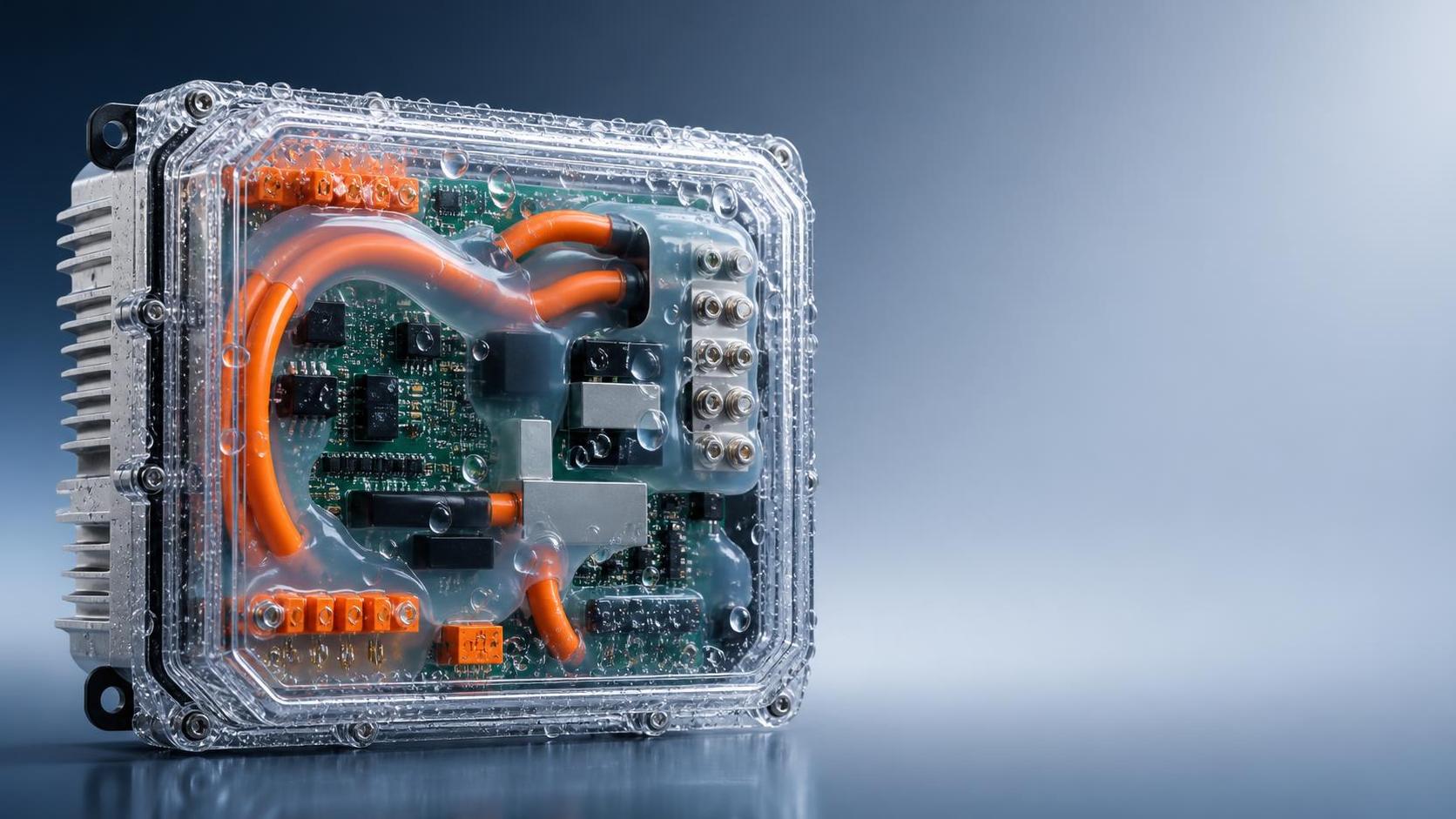
This is where silicone potting for power modules becomes relevant. A properly selected and processed silicone compound can reduce access paths for humidity and condensation, support dielectric isolation around energized conductors, and tolerate movement caused by thermal cycling. It is not, however, a universal cure. Potting can also trap contaminants, obstruct heat flow, place stress on delicate interconnects, or make a repairable module effectively disposable. The useful question is not whether to pot, but under which failure conditions silicone potting is the appropriate control.
Start with the moisture path, not the material name
When a module fails in damp conditions, it is tempting to specify a “waterproof” compound immediately. That skips the most important part of the investigation: identifying how water vapor, liquid water, or condensation reaches the vulnerable area.
Moisture does not always enter through an obvious crack. It can migrate along wire strands, through imperfect connector seals, between a housing and a lead frame, or through voids created during dispensing. In assemblies with large temperature changes, air inside the enclosure can expand and contract. This breathing action draws humid air through small gaps that might never admit visible liquid during a simple splash test.
Before changing the protection method, map the electrical regions that are sensitive to moisture. These usually include exposed high-voltage clearances, gate-drive areas, sensor circuits, terminal interfaces, soldered joints beneath leads, and the boundary between encapsulant and housing. A low-voltage control section may survive conditions that cause severe leakage in a high-voltage section. Treating the whole cavity as equally critical can lead to unnecessary material use and more difficult thermal management.
Symptoms that point toward internal moisture exposure
- Insulation or leakage measurements worsen after humidity exposure and recover after drying.
- Corrosion is concentrated around terminals, wire exits, plated surfaces, or housing seams.
- Failures occur after cold-to-warm transitions, when condensation is more likely than direct water contact.
- Electrical noise, false sensing, or gate-drive instability appears before a permanent short circuit develops.
- Disassembly reveals white residue, dendritic-looking deposits, darkened metal, or moisture tracks near air gaps.
None of these symptoms proves that potting is required. They do indicate that the investigation should include environmental sealing, cleanliness, surface energy, and mechanical movement—not only circuit design.
Cases where silicone is usually a strong candidate
Silicone compounds are commonly considered when a module needs environmental protection but cannot tolerate the rigidity of a hard epoxy encapsulant. Their low modulus can be valuable where power cycling causes the baseplate, substrate, terminals, and housing to move at different rates. If the protective material is too stiff, that movement may be transferred into solder joints, bond wires, ceramic substrates, or molded packages.
For power assemblies exposed to humidity and significant temperature variation, a compliant silicone can maintain contact with irregular geometry better than a rigid material. This matters around wire exits, terminal roots, sensor leads, and corners where a narrow gap can become a condensation site. Silicone may also be suitable where future rework is possible or where a component must be accessed for failure analysis, although actual removability depends on adhesion, geometry, cure condition, and the surrounding parts.
Silicone potting for power modules is particularly worth assessing when the design has a protected enclosure but still contains internal cavities, complex conductor geometry, or repeated condensation risk. It can also be useful when a conformal coating alone leaves exposed gaps around tall components, terminal transitions, or cable interfaces.
It is less automatically suitable when the principal problem is bulk heat removal. Many silicone potting materials provide some thermal transfer, but they should not be assumed to replace a well-designed heat path through the substrate, thermal interface, baseplate, housing, or heat sink. A module that already runs close to its thermal limit needs thermal analysis before adding a thick encapsulant layer, even if that layer is marketed as thermally conductive.
The common mistake: sealing a contaminated assembly
A potting compound can isolate a clean, dry assembly from future moisture. It cannot reverse contamination already present on the board or component surfaces. If residues, absorbed moisture, fingerprints, machining oils, flux activators, or cleaning-agent residues remain in the module, potting may preserve them in close contact with energized surfaces.
This is one reason early prototypes sometimes pass a short electrical check but later show leakage or corrosion after environmental exposure. The material itself may be compatible, yet the process created a closed environment around contamination. The problem is especially persistent beneath closely spaced leads and in corners that were difficult to rinse or dry.
Preparation should therefore be treated as part of the insulation system. Components, housings, and substrates need to be cleaned using a method compatible with their materials. After cleaning, sufficient drying time and controlled handling matter. A seemingly minor change, such as moving an assembly from a humid production area directly into potting, can introduce moisture that is not visible at the time of dispensing.
Questions to resolve before dispensing
First, determine whether the compound is intended to bond to the surfaces involved or simply fill the cavity. Strong adhesion can block moisture paths, but it can also complicate rework and concentrate stress at a boundary if the housing and encapsulant move differently. Weak adhesion may permit interfacial moisture travel. The appropriate balance depends on housing material, surface treatment, module geometry, and expected temperature range.
Second, confirm compatibility with plastics, cable jackets, labels, connector seals, solder masks, and exposed metals. Some materials are vulnerable to low-molecular-weight compounds, cure by-products, or prolonged contact with soft elastomers. Compatibility should be evaluated on representative construction, not inferred solely from a generic material description.
Third, inspect the cure mechanism. Condensation-cure silicones can be difficult to use in deep or poorly ventilated cavities because access to atmospheric moisture is limited. Addition-cure systems may be better suited to enclosed volumes, but their cure can be affected by contamination or certain materials. The selected system must cure reliably at the actual fill depth and under the available production conditions.
Design the fill pattern before selecting the final viscosity
Many void-related failures begin with a dispensing approach that was chosen for speed rather than flow behavior. A cavity filled from the top may appear full while trapping air beneath components, around terminals, or at sharp internal corners. Those voids can collect moisture, reduce dielectric distance, and create localized electric-field concentration.
A more reliable method is to define the flow route. In many geometries, dispensing from the lowest practical point and allowing the material to rise steadily helps move air toward vent locations. The aim is not always a rapid flood fill. A controlled flow can be more effective when the module contains narrow channels or densely packed conductors.
Viscosity affects both manufacturability and protection. A low-viscosity material can penetrate small gaps but may leak through incomplete seals or wick into areas that should remain clear, such as connector contacts or moving parts. A high-viscosity compound may stay where placed but can bridge over features and leave hidden voids. The correct choice depends on gap size, dispensing pressure, pot life, fill height, allowable cycle time, and whether vacuum assistance is available.
Thermal behavior must be evaluated as a system effect
Power modules generate heat unevenly. Semiconductor junctions, magnetic components, shunts, resistors, and bus structures may each have different allowable temperatures and different thermal paths. Filling a cavity changes convection, conduction, and sometimes the contact condition between components and the enclosure. The outcome cannot be judged from a single thermal conductivity figure.
A thermally conductive silicone can help connect selected surfaces to a housing, but it may also create an unintended route into temperature-sensitive control circuitry. Conversely, a low-conductivity silicone may reduce condensation risk while retaining more heat around a component that previously benefited from air circulation. Consider where heat originates, where it should exit, and whether the potting material bridges or blocks that route.
Thickness is important. A thin layer protecting exposed circuitry can behave very differently from a deep-filled module. Deep fills also generate more material volume, which can affect cure behavior and the practical difficulty of removing heat during production. The design review should include the maximum fill depth, not just the nominal cavity volume.
Use validation to separate a good material from a good process
Material qualification alone does not establish module reliability. The actual assembly process determines whether the material reaches intended surfaces, remains free of voids, and cures consistently. A useful validation plan combines inspection with electrical and environmental checks that match the expected service conditions.
Begin with representative assemblies, including realistic cable exits, terminal hardware, component population, and housing interfaces. Simple flat test coupons can support material screening, but they rarely reproduce the areas where moisture finds a path in a finished module. Record fill mass, dispense pattern, pot life exposure, cure schedule, and any vacuum or preheating conditions. These details make later failure analysis possible.
After cure, inspect for incomplete fill, surface craters, sink areas, separation at walls, and contamination in zones that must remain unpotted. Where geometry permits, sectioning a limited number of process samples can reveal void patterns that external inspection cannot see. Electrical measurements should be compared before and after relevant environmental conditioning, with attention to leakage, insulation behavior, functional stability, and temperature response.
Thermal cycling deserves particular attention because it tests more than the silicone itself. It stresses interfaces among the compound, housing, terminals, circuit board, and power devices. A material that remains soft is not automatically stress-free; geometry, adhesion, fill height, and local constraint all influence the result.
When potting is not the first fix
If moisture enters primarily through an external connector, cable gland, housing seam, or pressure-equalization feature, internal potting may only hide the symptom. Correcting the external ingress route can be more effective and may preserve serviceability. Likewise, if the failure comes from inadequate creepage and clearance, poor board cleanliness, or an unsuitable component package, adding encapsulant without addressing the underlying design weakness can create a false sense of security.
Conformal coating, selective gel application, gasket redesign, improved venting strategy, local barriers around sensitive nodes, and revised enclosure drainage may be better choices in some assemblies. A hybrid approach is common: protect the highest-risk electrical regions with silicone while leaving designated thermal interfaces, connectors, adjustment points, and service areas accessible.
A practical decision point before release
Silicone potting is justified when it addresses a defined moisture mechanism without creating unacceptable thermal, mechanical, manufacturing, or service consequences. The decision becomes stronger when the team can answer a few grounded questions: Where does moisture enter? Which energized areas are exposed? Will the compound cure fully at the required depth? Can the dispensing route avoid voids? Does the new fill arrangement preserve the intended heat path? And can the finished module be inspected and tested in a way that detects process drift?
If those answers remain uncertain, the next step is usually not a larger potting volume. It is a smaller, representative trial that examines cleanliness, flow, cure, interface adhesion, electrical insulation, and thermal behavior together. That approach turns silicone potting from a generic sealing step into a controlled reliability measure for power modules operating where moisture is a real design condition.
Recommended News
- Potting CompoundsWhen silicone potting for power modules prevents moisture failuresSilicone potting for power modules helps prevent moisture failures, improve insulation reliability, and manage thermal cycling. Explore key selection and process insights.
- Potting CompoundsHow to write a potting compound specification that manufacturers can followPotting compound specification guide: learn how to define clear, testable requirements manufacturers can follow to reduce sourcing risk, improve compliance, and ensure reliable electronic performance.
- Potting CompoundsHow Silicone Embedded Components Improve Sealing and Vibration ResistanceSilicone embedded components improve sealing and vibration resistance by reducing leaks, absorbing stress, and boosting long-term reliability in electronics, automotive, and industrial systems.
- Potting CompoundsEU RoHS Tightens Phthalate Limit for Potting CompoundsEU RoHS tightens phthalate limits for potting compounds to 0.1%, effective Oct 1, 2026. Learn who is affected, key compliance steps, and how to update CE files fast.
- Potting CompoundsTUV Rheinland Tightens Annex H for Potting CompoundsTUV Rheinland Tightens Annex H for Potting Compounds: learn how the new UL94 V-0 and CTI >=600V rules impact EU certification, sourcing, and supply-chain readiness.
- Potting CompoundsPCB Thermal Potting Lead Times Extend to 14 WeeksPCB Thermal Potting lead times now stretch to 14 weeks, disrupting Metal Core PCB, EV controls, and inverter delivery. See risks, causes, and smart planning actions.