
When does a high temperature thermal enclosure need active cooling?
DETAILS
When Does a High Temperature Thermal Enclosure Need Active Cooling?
A high temperature thermal enclosure is often specified to protect electronics from a hostile external environment: elevated ambient air, solar loading, hot process equipment, engine-adjacent installation, or a sealed industrial location where heat cannot easily escape. The enclosure may use insulation, reflective surfaces, conductive paths, heat shields, or thermal mass to slow heat transfer. Those measures can be highly effective, but they do not automatically solve the internal heat problem.
Active cooling becomes necessary when the heat entering and generated within the enclosure exceeds what its passive design can reject while keeping every critical component within its allowable operating and reliability limits. That sounds straightforward, yet it is frequently misjudged because the enclosure air temperature is only one part of the thermal picture. Junction temperatures, board-level hot spots, transient power profiles, cable heat conduction, and the duration of exposure can all change the answer.
For a technical evaluator, the key question is not whether an enclosure is labeled “high temperature.” It is whether the complete thermal path—from semiconductor junction to ambient environment—remains acceptable under the worst credible operating condition.
The Basic Decision: Can Passive Heat Rejection Close the Thermal Balance?
Every enclosure design should begin with a heat balance. Internal electronics dissipate power. External conditions add heat through the walls, mounting structure, connectors, windows, and sometimes direct radiation. Heat must then leave through some combination of conduction, convection, radiation, or stored thermal capacity. If the outgoing heat flow is lower than the incoming heat flow over the required mission period, internal temperature will continue to rise.
A simplified steady-state relationship is useful for screening:
Temperature rise ≈ total heat load × thermal resistance to ambient.
The relationship is not enough for final qualification, particularly where heat loads are transient or insulation properties change at temperature, but it reveals the central issue. A heavily insulated enclosure may reduce heat entering from outside while also making it harder for internally generated heat to leave. In other words, insulation can protect the electronics during a short external heat event and still create an overheating problem during continuous operation.
Passive cooling may remain appropriate where internal dissipation is low, exposure is brief, the permitted internal temperature is relatively high, and the enclosure has a credible conductive or radiative route to a cooler sink. Active cooling should move from “optional” to “required for evaluation” when those assumptions no longer hold.
The Conditions That Usually Trigger Active Cooling
The strongest indicator is a sustained internal heat load in a sealed or highly insulated volume. Power converters, RF modules, processors, optical engines, battery-management electronics, motor drives, and densely populated control boards can dissipate enough heat that natural convection inside the housing is insufficient. Heat may accumulate around the component even before the bulk air temperature appears alarming.
High ambient temperature is the second major trigger. A fan moves heat only if a cooler heat sink exists. When outside air is already close to the maximum allowable enclosure temperature, forced-air cooling may improve internal uniformity but cannot create useful cooling capacity on its own. This is where a liquid loop, refrigerated heat exchanger, thermoelectric device, phase-change approach, or remote heat sink may be considered. Each has material, power, maintenance, and reliability consequences that should be evaluated rather than assumed.
Another trigger is a narrow margin between the enclosure environment and component-level temperature ratings. Semiconductor data sheets typically distinguish ambient, case, board, and junction limits. A board may remain technically within its ambient rating while a high-power device exceeds its junction-temperature limit because of package thermal resistance, interface degradation, poor spreading through copper planes, or uneven airflow. Thermal derating curves, if provided by the component manufacturer, should be treated as design inputs rather than last-minute troubleshooting tools.
Mission duration matters as much as peak temperature. A passive design can survive a short pulse through thermal mass or phase-change storage, then fail during a long dwell when the stored capacity is exhausted. Conversely, a continuously powered system may require active cooling even if its external environment is less severe than a short-duration hot test. Evaluators should specify the full duty cycle: start-up, high-load operation, idle state, shutdown, restart behavior, and recovery time between cycles.
Do Not Use Enclosure Air Temperature as the Only Acceptance Criterion
A common procurement mistake is to ask whether the enclosure can maintain a stated internal air temperature, without identifying what needs protection and where it is located. The component most likely to limit the design may be a power transistor, FPGA, capacitor, magnetic component, adhesive, connector insert, sensor, or battery cell. These parts do not respond to heat in the same way.
For example, semiconductors are generally governed by junction temperature and temperature cycling. Passive components may be more sensitive to material drift, electrolyte life, solder-joint fatigue, or mechanical stress from unequal expansion. PCB reliability can be affected by localized gradients, repeated cycling, resin system selection, copper distribution, via architecture, and moisture history. A thermal enclosure that protects one device category may still impose unacceptable long-term stress on another.
This is especially relevant in high-density EMS assemblies. The thermal result is shaped not only by enclosure architecture but by PCB stack-up, copper weight, thermal-via implementation, component placement, heat-sink attachment, solder process consistency, and the actual power map of the assembly. A nominally identical board can exhibit different hot-spot behavior when manufacturing tolerances or material substitutions change the thermal path.
Passive, Forced-Air, and Closed-Loop Approaches Serve Different Problems
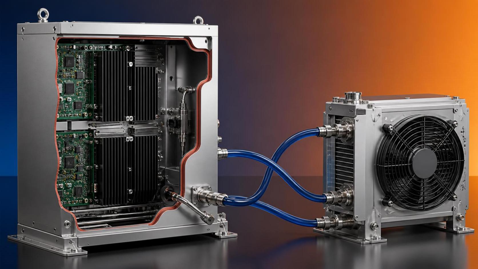
The choice is not simply passive versus active. A well-designed system commonly combines them. Insulation may reduce solar or process heat gain; conductive interfaces may move concentrated device heat to the wall; forced circulation may remove local stagnation; and a closed-loop cooler may provide the final heat rejection margin. The architecture should match the dominant thermal resistance, not follow a generic enclosure catalog option.
Warning Signs That a Passive Proposal Is Under-Specified
Technical reviewers should be cautious when a proposal presents only an enclosure material rating or insulation thickness. Those details matter, but they do not establish the internal operating temperature. The design needs a defined ambient profile, solar or radiant loading where relevant, internal dissipation by operating mode, enclosure geometry, mounting orientation, external airflow assumptions, and a thermal path from major heat sources to the enclosure boundary.
Other warning signs include a single temperature sensor located away from the hot spot, no stated interface material between a power device and heat sink, no allowance for dust accumulation on external fins, or a cooling fan assumed to operate indefinitely at elevated temperature. For outdoor and industrial systems, ingress protection can also conflict with ventilation. Open vents may help thermal performance but introduce humidity, particles, corrosive contaminants, and water-entry concerns. A sealed design with an external heat exchanger often avoids that trade-off, though it creates its own integration requirements.
Thermal cycling deserves equal attention. Even where steady-state temperature is acceptable, frequent transitions can strain solder joints, connectors, potting compounds, thermal pads, and multilayer PCB structures. Active cooling with poorly tuned control logic can aggravate cycling by repeatedly forcing rapid temperature changes. The preferred control strategy is therefore not always the coldest possible internal temperature; it is a stable, supportable operating range that respects component limits and expected life.
Build the Requirement Around the Worst Credible Operating State
Before selecting active cooling, define what “worst case” means for the application. It should include the highest credible ambient condition, maximum internal power dissipation, constrained external airflow, anticipated radiation sources, and the required operating duration. If the equipment may be installed in several orientations or mounting configurations, each can change convection and conductive heat rejection. Cable harnesses and structural attachments should also be considered: they may either import heat from nearby equipment or provide an unexpectedly useful heat path.
Then translate the system requirement into component-level limits. Identify the critical devices, their maximum allowed junction, case, board, or storage temperatures, and any derating requirements. Separate functional limits from reliability targets. Operating close to an absolute maximum rating may be technically permissible under a data sheet, but it is rarely a sound basis for a long-life industrial design without a broader qualification rationale.
The verification plan should reflect the uncertainty in the thermal model. Simulation is valuable for comparing architectures and locating likely hot spots, but it depends on realistic material properties, contact resistances, power maps, and boundary conditions. Physical testing should use representative assemblies and instrument both enclosure air and critical component locations. Where manufacturing variation is meaningful, evaluators should determine whether the tested unit represents production intent, including PCB construction, component sources, assembly process, heat-sink interfaces, and firmware-controlled load behavior.
Cooling Hardware Changes the Reliability and Supply-Chain Question
Adding active cooling is not a purely thermal decision. Fans, pumps, compressors, valves, sensors, controllers, filters, and power supplies introduce new failure modes. Their operating temperature ratings, ingress protection, noise constraints, redundancy strategy, maintenance access, and availability should be reviewed alongside cooling capacity. A system that meets a thermal test but cannot maintain its cooling hardware in the intended environment may not meet the actual mission.
For semiconductor and EMS programs, this also means validating the data trail behind the design. Material substitutions, changes in fan bearing technology, alternate thermal interface materials, revised PCB dielectric systems, or different component packaging can alter thermal behavior without changing the outward appearance of the product. Independent benchmarking is useful when supplier documentation is incomplete or when several manufacturing sources must be compared on a common basis.
SiliconCore Metrics approaches this type of evaluation as a data problem rather than a catalog comparison. Its research across PCB fabrication, SMT assembly, active and passive components, and thermal packaging is intended to help engineering and procurement teams connect thermal claims to the underlying manufacturing parameters. For designs expected to align with requirements such as IPC Class 3 or ISO 9001-controlled production, the relevant question is not whether a label appears in a supplier file. It is whether the specific materials, processes, inspection evidence, and environmental assumptions support the required application.
A Practical Decision Point
A high temperature thermal enclosure needs active cooling when passive measures cannot maintain acceptable component-level temperatures for the full worst-case mission, with adequate allowance for production variation, fouling, aging, and control behavior. It may also need active cooling when the internal setpoint must remain below the available ambient heat sink, even if internal power dissipation is modest.
The most defensible selection process begins with a complete heat-load profile and ends with component-level verification under representative conditions. If the passive concept only works by assuming lower power, cooler ambient air, a shorter duty cycle, or ideal heat-transfer surfaces, it is not yet a reliable thermal architecture. That is the point at which active cooling—or a redesign of the electronics, enclosure, and mounting path—should be assessed before the design reaches production.
Recommended News
- Heat DissipationHow to prevent overheating in automotive PCB power distributionPrevent overheating in automotive PCB power distribution with practical tips on copper layout, thermal paths, and testing. Discover how to reduce hotspots and improve reliability.
- Heat DissipationCan heat spreading intelligence identify hot spots in PCB designs?Discover how heat spreading intelligence identifies PCB hot spots before fabrication. Learn to assess thermal models, validate predictions, and choose design changes that improve reliability.
- Heat DissipationWhich heat sink materials suit high-power electronics made in Germany?Heat sink materials Germany: compare aluminum, copper, graphite, and hybrid designs for high-power electronics. Find the right balance of thermal performance, weight, cost, and manufacturability.
- Heat DissipationHow to assess a graphite materials supplier's capability for thermal partsGraphite materials supplier assessment starts with more than machining. Discover how to evaluate thermal performance, purity, precision, cleanliness, traceability, and testing for reliable thermal parts.
- Heat DissipationHow to assess a heat dissipation supplier before placing an orderHeat dissipation supplier assessment guide: verify thermal performance, materials, process control, samples, capacity, and total risk before placing an order.
- Heat DissipationHow automotive PCB material selection affects thermal reliabilityAutomotive PCB material selection shapes thermal reliability. Explore CTE, Tg, moisture resistance, stack-up design, and proven qualification strategies for demanding vehicle electronics.