
What Thermal Conductivity Is Enough for Heat Sink Paste?
DETAILS
A heat sink paste rated at 12 W/m·K can look like an obvious upgrade over one rated at 5 W/m·K. Yet once both are installed, the temperature difference may be small—or the lower-rated material may perform better. That is frustrating when you are trying to recover thermal margin or approve a second-source material without introducing new manufacturing risks.
What thermal conductivity threshold matters most for heat sink paste? The useful threshold is the one that keeps the installed interface within its temperature-rise budget. For many conventional, thin-bond-line applications, compounds in the approximate 3–8 W/m·K range are reasonable candidates for evaluation. That is a screening range, not a universal specification. Bond-line thickness, contact resistance, mounting pressure, and aging can matter as much as the advertised conductivity.
The practical question is not “Which paste has the largest number?” It is “Which material delivers sufficiently low, repeatable thermal resistance in our assembly, throughout its service life?”
Start with the temperature rise you can afford
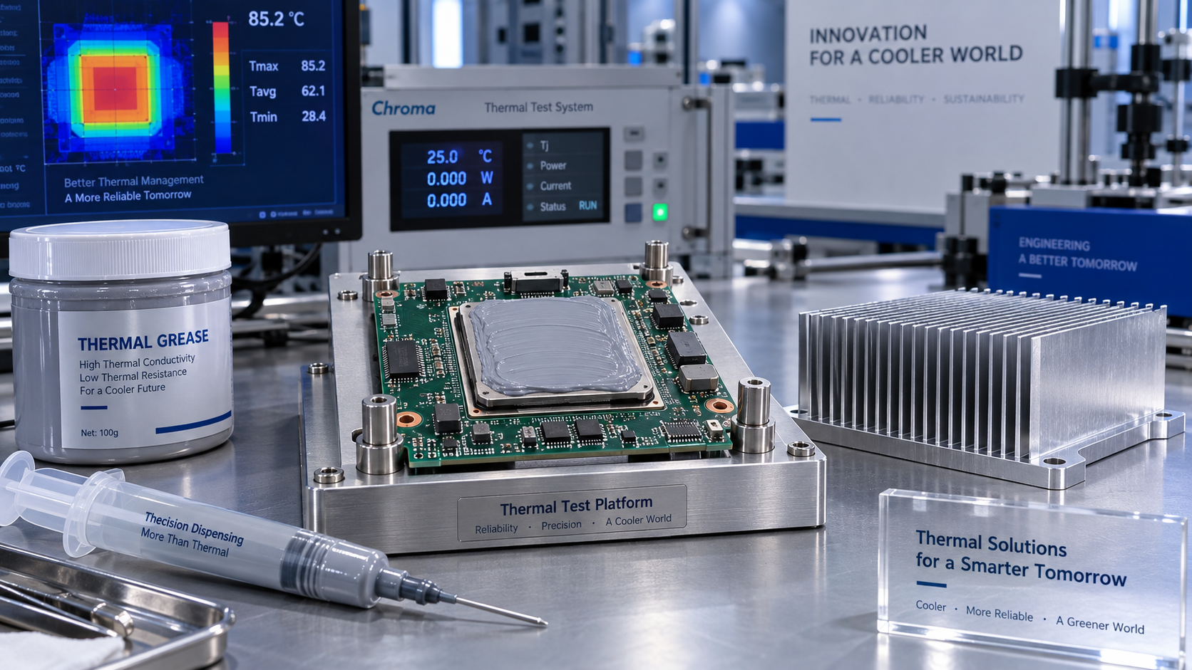
Heat sink paste fills microscopic gaps between mating surfaces. Without it, trapped air impedes heat transfer even when the component and heat sink appear to touch. The paste improves this interface, but it is generally much less conductive than the adjoining metals. A thicker layer therefore usually adds thermal resistance rather than improving cooling.
For a simplified, uniform interface, the paste layer’s bulk thermal resistance is:
Rbulk = t / (k × A)
- t is the installed bond-line thickness in meters.
- k is thermal conductivity in W/m·K.
- A is the effective heat-transfer area in square meters.
The temperature rise across that layer is approximately heat flow multiplied by thermal resistance. However, the complete interface also includes resistance where the paste contacts each surface:
Rinterface ≈ t / (k × A) + Rcontact,1 + Rcontact,2
This distinction changes purchasing decisions. Increasing conductivity reduces the bulk term; it does not automatically fix poor wetting, surface contamination, insufficient pressure, or voids. In a real assembly, heat spreading and nonuniform loading can further limit the accuracy of this simple model.
A worked example: turning a cooling target into a conductivity requirement
Consider a hypothetical component transferring 100 W through a 20 mm × 20 mm interface. Suppose the thermal design allows a 5°C rise across the entire paste interface, and the expected bond line is 50 µm thick.
The allowable interface resistance is 5°C ÷ 100 W, or 0.05 K/W. Ignoring contact resistance initially, the minimum calculated conductivity is:
k = 0.00005 / (0.05 × 0.0004) = 2.5 W/m·K
That is an idealized lower bound—not a safe procurement threshold. If the two contact terms together consume 0.03 K/W, only 0.02 K/W remains for the paste layer. The calculated conductivity requirement then becomes 6.25 W/m·K.
Those contact values are illustrative, not assumed properties of a particular product. The lesson is that the same heat load, area, and thickness can produce very different conductivity requirements depending on interface quality. Allow additional margin for manufacturing variation and aging, then validate the result experimentally.
What conductivity range is enough for your application?
A conductivity band can help build a shortlist, provided it is treated as an engineering starting point. The following ranges are approximate screening categories for conventional thermal pastes, not standardized performance classes.
A low-power controller with a large contact area may gain little from moving above the middle band. A compact power device with a small footprint and tight temperature limit may need higher conductivity, a thinner interface, or a different thermal interface material altogether.
Processor power alone is not enough to select a paste. Package construction, heat-spreader geometry, local heat flux, cooler flatness, and mounting mechanics all affect the interface. Two devices dissipating the same total wattage can impose very different thermal demands.
Why a higher W/m·K rating can stop helping
Imagine the example interface with a fixed 50 µm bond line and 400 mm² area. At 5 W/m·K, its calculated bulk resistance is 0.025 K/W. At 10 W/m·K, that falls to 0.0125 K/W. At 100 W, doubling conductivity reduces the bulk-layer temperature rise by just 1.25°C.
That improvement may be valuable near a throttling limit. It may also be smaller than temperature variation caused by mounting, fan control, ambient conditions, or measurement uncertainty. The rest of the thermal path—package, heat sink, and heat rejection to the environment—does not improve simply because the paste rating doubles.
Bond-line thickness can erase the advantage altogether. Under the same simplified assumptions, a 10 W/m·K paste installed at 100 µm has the same bulk resistance as a 5 W/m·K paste installed at 50 µm.
This does not mean thinner is always better without qualification. The layer must still accommodate surface roughness and flatness variation without leaving dry regions. The objective is the thinnest reliable, fully wetted interface permitted by the assembly, not an arbitrarily minimal amount of paste.
Read the datasheet as a test report, not a ranking
Conductivity values are only meaningfully comparable when the measurement methods and conditions are understood. Supplier numbers may come from different techniques, specimen preparation procedures, temperatures, or data-reduction methods. A precise-looking value does not guarantee comparable evidence.
For engineering and procurement teams, the more useful request is often thermal impedance or interface resistance versus bond-line thickness and pressure. ASTM D5470 is a relevant method for evaluating thermal transmission properties of thermally conductive electrical insulation materials and is commonly referenced for thermal interface characterization. A reference to the method still requires scrutiny of the actual setup and reported conditions.
Ask suppliers to clarify:
- Whether the value represents bulk conductivity or an interface measurement.
- The test temperature, applied pressure, thickness range, and mating surfaces.
- Whether contact resistance was separated from bulk resistance.
- The units, sample count, and measurement uncertainty.
- Whether results describe fresh material or material after environmental exposure.
Pay particular attention to units. Thermal conductivity in W/m·K is not interchangeable with resistance in K/W or area-normalized impedance in K·cm²/W. When comparing area-normalized results, use consistent units and confirm that the application’s pressure and thickness are represented.
At SiliconCore Metrics, the emphasis on independent benchmarking and standardized technical reporting is especially relevant here: normalize the evidence before ranking the materials. Quality-system certification can support supplier qualification, but ISO 9001 does not verify a paste’s conductivity or prove its suitability for a specific interface. Likewise, IPC Class 3 requirements should not be treated as a standalone thermal-paste performance certification.
The threshold has to survive the production line—and the field
A paste that performs well during a carefully controlled bench test may behave differently after automated dispensing, shipment, and years of thermal cycling. For EMS operations, manufacturability is part of thermal performance.
Dispensing and mounting determine the starting condition
Viscosity, filler size, storage history, and process temperature affect how consistently material can be deposited. An overly stiff compound may resist spreading under the available mounting load. An uncontrolled deposit can produce excess thickness, incomplete coverage, or trapped air.
Specify deposit quantity, pattern, mounting procedure, and inspection criteria together. Torque alone does not always provide a reliable estimate of interface pressure; fastener friction and assembly geometry influence the actual load. For exposed dies, mechanical limits are particularly important: increasing pressure is not a free thermal improvement.
Aging determines whether the starting condition lasts
Thermal cycling can promote pump-out as adjoining materials expand differently. Some formulations may experience carrier separation, migration, or dry-out under particular operating conditions. The resulting loss of coverage can outweigh an initially superior conductivity rating.
Qualification should therefore examine resistance after relevant thermal cycling, powered cycling, high-temperature storage, or other application-specific stresses. No single accelerated test represents every field environment. Choose conditions that reflect the device’s temperature excursions, orientation, materials, and expected duty cycle.
Electrical compatibility also belongs in the decision. Thermal conductivity does not establish electrical insulation. Review resistivity, dielectric properties where relevant, and risks from squeeze-out near exposed circuitry. Liquid-metal materials require a separate compatibility assessment, including electrical conduction and interaction with adjoining metals; they are not drop-in substitutes for conventional paste.
A practical qualification path for engineers and buyers
Rather than setting an arbitrary “minimum 10 W/m·K” requirement, build the specification around an installed performance target.
- Allocate the thermal budget. Determine how much temperature rise is available for the interface after accounting for the package, heat sink, ambient conditions, and design margin.
- Characterize the mechanics. Establish effective area, flatness, mounting load, and achievable bond-line thickness. If the gap is substantial or poorly controlled, evaluate whether a pad, gap filler, or another interface format is more suitable.
- Screen candidates using comparable data. Use conductivity to narrow the list, then compare interface resistance under representative conditions.
- Test the actual assembly. Control power, ambient temperature, airflow, mounting procedure, and measurement location. Repeat installations so one unusually good mount does not determine the result.
- Check retained performance. Repeat thermal measurements after relevant aging and inspect for migration, coverage loss, and compatibility issues.
- Lock down production requirements. Document storage, shelf life, dispensing controls, acceptance limits, traceability, and supplier change-notification expectations.
For a second source, matching the incumbent’s headline conductivity is insufficient. The replacement needs to meet the same installed thermal and reliability limits, even if its viscosity or recommended process window differs.
The number worth putting on the specification
For many assemblies, 3–8 W/m·K is a sensible place to begin evaluating conventional heat sink paste. It is not a guarantee of adequacy, and exceeding that range is not automatically wasteful. Higher conductivity becomes worthwhile when bulk-layer resistance is a significant constraint and testing confirms a useful improvement.
The strongest specification states a maximum interface resistance at defined thickness, pressure, and temperature, together with an allowable change after relevant aging. Conductivity can remain a supporting requirement, but it should not carry the entire decision.
Enough thermal conductivity means the interface stays within its temperature budget, can be assembled consistently, and retains that performance in service. Once those conditions are met, a larger number on the datasheet is optional—not the definition of a better paste.
Recommended News
- Heat DissipationWhich thermal interface quality metrics matter after thermal cycling?Explore thermal interface quality metrics after thermal cycling, from retained resistance to contact integrity. Learn how to set acceptance criteria and qualify materials with confidence.
- Heat DissipationHow to prevent overheating in automotive PCB power distributionPrevent overheating in automotive PCB power distribution with practical tips on copper layout, thermal paths, and testing. Discover how to reduce hotspots and improve reliability.
- Heat DissipationWhat Thermal Conductivity Is Enough for Heat Sink Paste?What thermal conductivity threshold matters most for heat sink paste? Explore the 3–8 W/m·K screening range and learn how thickness, contact resistance, and aging guide smarter selection.
- Heat DissipationCan heat spreading intelligence identify hot spots in PCB designs?Discover how heat spreading intelligence identifies PCB hot spots before fabrication. Learn to assess thermal models, validate predictions, and choose design changes that improve reliability.
- Heat DissipationWhich heat sink materials suit high-power electronics made in Germany?Heat sink materials Germany: compare aluminum, copper, graphite, and hybrid designs for high-power electronics. Find the right balance of thermal performance, weight, cost, and manufacturability.
- Heat DissipationHow to assess a graphite materials supplier's capability for thermal partsGraphite materials supplier assessment starts with more than machining. Discover how to evaluate thermal performance, purity, precision, cleanliness, traceability, and testing for reliable thermal parts.