
Power Semiconductor Selection: Prioritize Efficiency or Cost?
DETAILS
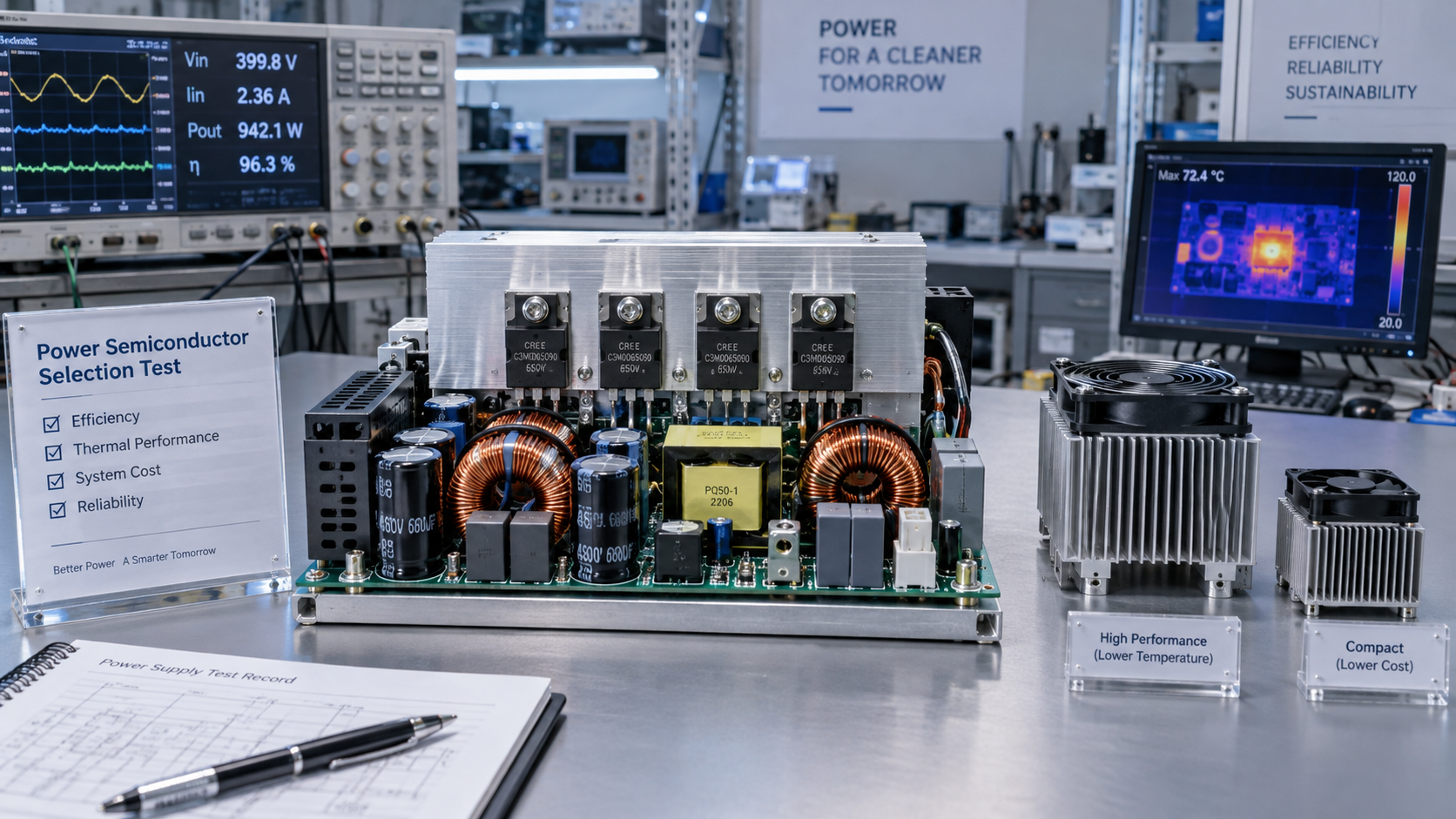
Should I prioritize energy efficiency or cost when selecting power semiconductors? The practical answer is to prioritize the lowest total system cost that still meets your electrical, thermal, and reliability requirements. Device price matters, but it is only one line in that calculation.
A less expensive transistor can become an expensive choice if it requires a larger heat sink, forces a lower switching frequency, or consumes more electricity over years of operation. Conversely, paying a premium for silicon carbide (SiC) or gallium nitride (GaN) makes little sense when the application rarely operates at the conditions where those devices deliver their advantage.
For design engineers and procurement teams, the challenge is not choosing between “cheap” and “efficient.” It is determining which performance improvements have measurable value—and which merely look impressive in a datasheet.
Start with the operating profile, not the semiconductor material
Before comparing silicon, SiC, and GaN, define what the converter will actually do. A power supply running continuously near rated output has different priorities from a motor drive with frequent acceleration cycles or a consumer device that spends most of its life in standby.
The following inputs establish a useful selection baseline:
- Voltage and transient exposure: Include bus variation, switching overshoot, and abnormal operating conditions—not just nominal voltage.
- Current profile: Identify average, RMS, peak, and fault currents, including startup and overload events.
- Switching frequency and topology: Hard switching, soft switching, and reverse-current operation change the loss balance.
- Load distribution: Estimate time spent at light, medium, and full load.
- Thermal environment: Account for enclosure temperature, airflow, cooling constraints, and adjacent heat sources.
- Service expectations: Define operating hours, design life, maintenance access, and acceptable downtime.
These details prevent a common mistake: optimizing efficiency at a single test point that does not represent normal use. A converter with excellent full-load efficiency may still consume more annual energy than an alternative with better performance across its dominant load range.
Where the efficiency difference actually comes from
Power semiconductor losses are not a single number. They arise from several mechanisms, and improving one can worsen another.
Conduction losses: resistance is only part of the comparison
For a MOSFET, a useful first approximation is Pcond = IRMS2 × RDS(on), using the current through the device over the relevant interval. The resistance must reflect the expected junction temperature and gate-drive voltage. Comparing room-temperature headline values can understate real operating losses.
IGBT conduction loss is better evaluated from collector-emitter voltage versus current over the operating waveform, rather than from an on-resistance model. Diodes likewise require attention to forward voltage, conduction duration, and temperature.
A larger MOSFET die may reduce resistance, but it can also increase gate charge and capacitance. The lowest-resistance option is therefore not automatically the most efficient choice at high switching frequency.
Switching losses: the circuit matters as much as the device
A common starting estimate is Psw ≈ (Eon + Eoff) × fsw. However, switching-energy figures depend on voltage, current, gate resistance, temperature, and the commutating device used during measurement. Datasheet results obtained under different conditions are not directly comparable.
Other contributors include gate-drive power, output-capacitance energy, diode reverse recovery, and dead-time conduction. In soft-switching designs, some switching losses may fall substantially, changing the relative advantage of competing technologies.
Fast switching also introduces practical costs. Higher voltage and current slew rates can increase electromagnetic interference, overshoot, and sensitivity to PCB layout. Gate tuning, snubbers, filtering, and careful loop design may be necessary to turn a promising device into a compliant product.
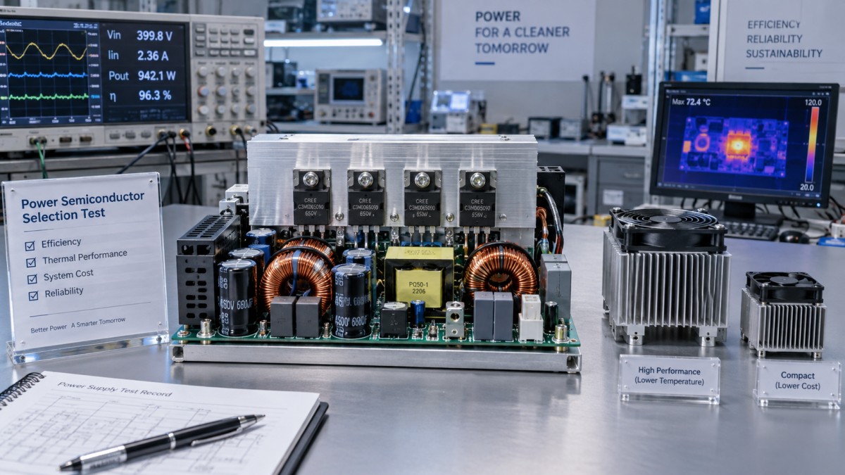
The useful comparison is therefore not “Which transistor has the best specifications?” It is “Which device produces the lowest verified losses in this topology, with acceptable EMI and adequate operating margins?”
Silicon, SiC, or GaN: match the advantage to the application
Material choice narrows the search, but it does not replace device-level evaluation. Packages, voltage classes, gate requirements, and supplier implementations vary considerably.
Silicon remains a strong engineering choice when its performance comfortably meets the design targets. Mature availability and familiar implementation can reduce development effort as well as purchase cost.
SiC or GaN becomes more attractive when its characteristics remove a system bottleneck. That might mean reducing cooling hardware, increasing switching frequency to shrink magnetics, or meeting an efficiency requirement that silicon cannot achieve economically.
Do not assume those benefits arrive together. Increasing switching frequency may reduce passive-component size while consuming some of the efficiency gain. The design team must decide how to spend the technology’s performance advantage.
Translate better efficiency into a financial decision
A useful comparison separates three cost categories: acquisition, operation, and risk. Acquisition includes the semiconductor, gate driver, cooling assembly, magnetics, PCB, filtering, and manufacturing effort. Operation covers electricity and applicable cooling or maintenance expenses. Risk includes supply disruption, redesign, and field failures.
For a constant output power, input power is Pin = Pout / η, where efficiency η is expressed as a decimal. The energy benefit of a higher-efficiency design follows from the difference in input power over its operating hours.
Consider an illustrative 10 kW converter operating at that output for 4,000 hours annually. Raising efficiency from 97% to 98% reduces input power by approximately 105 W. That saves roughly 421 kWh per year. At an assumed electricity price of $0.12/kWh, the annual saving is about $50.
If the higher-efficiency design adds $150 to the system cost, the simple energy-only payback is approximately three years. These are hypothetical inputs, not measured device results or market quotations. Actual savings depend on load distribution, energy tariffs, and operating hours.
The calculation becomes more useful when the system changes are included:
- A smaller heat sink or cooling assembly can offset part of the semiconductor premium immediately.
- A more expensive driver, additional EMI filtering, or a more demanding PCB stack-up can reduce that offset.
- Lower dissipation can provide thermal margin, but longer service life requires evidence rather than assumption.
- For short-lived or lightly used equipment, energy savings may never recover the additional purchase cost.
For longer-lived assets, compare discounted lifetime costs rather than relying only on simple payback. Where the equipment owner pays the energy bill but the manufacturer pays the component premium, the business case also needs a clear way to communicate that lifetime value.
When should efficiency take priority over initial cost?
Prioritize efficiency when losses impose a meaningful operating expense or prevent the product from meeting a hard requirement. Continuous-duty industrial power supplies, renewable-energy converters, and densely packaged equipment often fall into this category.
Efficiency can also deserve priority when cooling capacity is fixed. If the enclosure cannot accommodate another fan or a larger heat sink, a lower-loss semiconductor may be the simplest way to preserve output power. Here, efficiency is not merely an energy-saving feature; it is a design constraint.
Prioritize initial cost when the lower-priced solution already meets performance targets with sufficient margin and lifetime savings are small. Low-utilization equipment and applications with generous thermal space may fit this profile. The decision still requires loss calculations and validation: “cost-sensitive” should not become an excuse for running close to thermal or voltage limits.
Between those extremes, sensitivity analysis is more useful than a categorical answer. Test how the decision changes with operating hours, electricity price, device premium, cooling cost, and expected service life. If small changes reverse the conclusion, keep both options open until better application data is available.
Validate the design—and the supply chain
Simulation can narrow a shortlist, but hardware testing should confirm it. Measure efficiency across representative loads and temperatures, then inspect switching waveforms, device temperatures, and EMI behavior under realistic enclosure and cooling conditions.
A strong validation plan also checks startup, shutdown, overload, and relevant fault events. Short-circuit capability, avalanche behavior, and safe operating area are device-specific; they should never be inferred solely from the semiconductor material.
Procurement review should run alongside electrical testing, not after it. A technically attractive device can create avoidable exposure if it has limited sourcing options, uncertain lifecycle support, or a package that makes substitution difficult.
Request evidence covering traceability, qualification, manufacturing change notifications, and relevant reliability testing. Compare potential substitutes carefully: a matching voltage rating and package do not guarantee equivalent gate-drive behavior, thermal performance, or switching characteristics.
This is where an independent benchmarking perspective, such as that described by SiliconCore Metrics (SCM), becomes useful. Standardized comparison conditions help engineers and procurement teams distinguish genuine performance advantages from differences in test methodology. Semiconductor data should also be considered alongside PCB parasitics, assembly quality, and thermal-interface performance.
Keep standards in their proper context. ISO 9001 concerns quality-management systems; it does not prove that a particular power device is reliable in your application. IPC Class 3 requirements may be relevant to PCB and assembly quality, but they are not a standalone semiconductor qualification. Each claim needs evidence appropriate to the component and its intended use.
Make the trade-off visible before approving the part
The final selection should fit on a concise comparison sheet: verified losses at representative operating points, junction-temperature margin, complete system cost, expected energy consumption, validation results, and sourcing risk.
Avoid collapsing everything into a weighted score too early. Hard requirements—voltage margin, thermal limits, fault response, or compliance—must be passed before commercial preferences are balanced.
When both options meet those requirements, choose the one with the better supported lifetime value. Sometimes that will be a familiar silicon device with a modest purchase price. Sometimes it will be SiC or GaN, whose premium is recovered through lower losses or a smaller system.
The sound decision is neither “efficiency at any cost” nor “the cheapest semiconductor available.” It is the least costly, adequately validated solution for the way the product will actually operate.
Recommended News
- Power SemiPower Semiconductor Selection: Prioritize Efficiency or Cost?Should I prioritize energy efficiency or cost when selecting power semiconductors? Compare silicon, SiC and GaN to reduce lifetime costs without compromising reliability.
- Power SemiHow to reduce lead-time risk in 24V component sourcing24V component sourcing made resilient: learn how to qualify alternates, verify lead times, control quality risk, and keep production moving.
- Power SemiWhich semiconductor quality metrics best predict field reliability?Semiconductor quality metrics that best predict field reliability: evaluate parametric drift, stress-test relevance, package integrity, screening coverage, and true mission-profile margin.
- Power SemiWhat Is the Biggest Risk of Skipping Power Electronics Supplier Audits?What is the biggest risk when skipping supplier audits for power electronics? Hidden reliability failures, weak traceability, and costly field failures. Learn how audits protect quality.
- Power SemiHow to qualify semiconductor power devices for reliable switching performanceSemiconductor quality power devices: learn how to qualify switching margins, thermal reliability, gate-drive behavior, and production consistency for demanding converters.
- Power SemiHow to Evaluate Energy Saving Semiconductor Solutions for High-Efficiency Power DesignEnergy saving semiconductor solutions for high-efficiency power design: learn how to compare loss, thermal, EMI, reliability, and supply chain factors to choose the right device.