
How Does FPC Bend Radius Affect Wearable Device Lifespan?
DETAILS
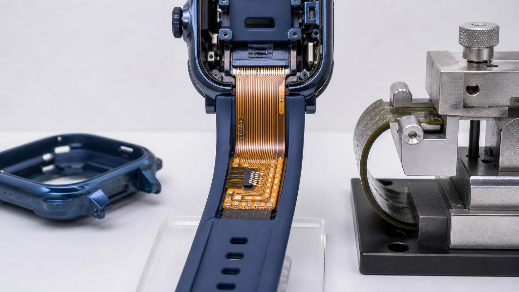
How does FPC bend radius impact circuit lifespan in wearable devices? More directly than many early design reviews suggest. In a smartwatch strap, an ECG patch, a hearing device, or a motion-tracking garment, a flexible printed circuit is not simply routed through a tight space. It becomes part of the product’s moving anatomy. Every wrist rotation, clasp adjustment, stretch, fold, and drop can add mechanical strain to copper conductors, coverlay, adhesive interfaces, and soldered transition points.
A flexible circuit can look flawless after assembly and still fail months later because its bend region was designed around package geometry rather than real use. The question is therefore not only whether an FPC can bend once during installation. Engineers need to ask how far it bends, how often, where the bend occurs, and whether the material stack-up is appropriate for repeated movement.
For wearable teams balancing thinness, comfort, battery volume, and reliability, bend radius is a lifespan variable—not a cosmetic routing detail.
Why a smaller bend radius creates a larger reliability risk
Bend radius is the radius of the curve formed when an FPC is bent. A large radius creates a gradual curve; a small radius forces the circuit into a sharper fold. As the radius decreases, the outer layers of the flex stack are stretched while the inner layers are compressed. Copper traces on the tensile side experience the greatest fatigue exposure, particularly when the same location flexes repeatedly.
The underlying relationship is straightforward: strain rises as the bend radius becomes tighter. For a simplified flex layer, surface strain is often approximated as:
Strain ≈ material distance from the neutral axis ÷ bend radius
The neutral axis is the part of the stack-up that experiences the least elongation and compression during bending. In a symmetric construction, it may sit near the center. In a real wearable FPC, however, asymmetric copper distribution, stiffeners, coverlay thickness, adhesive layers, shielding, and bonded components can shift that neutral axis. That is why two circuits with the same overall thickness may not survive the same flexing duty.
A tight bend does not automatically mean immediate failure. The more important issue is accumulated damage. During repeated motion, copper can develop microcracks. Those cracks may slowly increase electrical resistance, create intermittent opens during movement, or eventually break a conductor completely. In fine-pitch signal paths, even small changes in conductor continuity or impedance can become visible as sensor noise, charging instability, display artifacts, or communication dropouts.
Static bends and dynamic bends should never be treated as the same condition
One of the most consequential distinctions in flexible circuit design is whether a bend is static or dynamic.
A static bend occurs when the FPC is folded or curved during assembly and then remains in roughly the same position throughout service. A flex tail tucked beneath a wearable’s housing is a common example. This condition still requires sensible bend-radius control, but its fatigue demand is comparatively limited once the product is assembled.
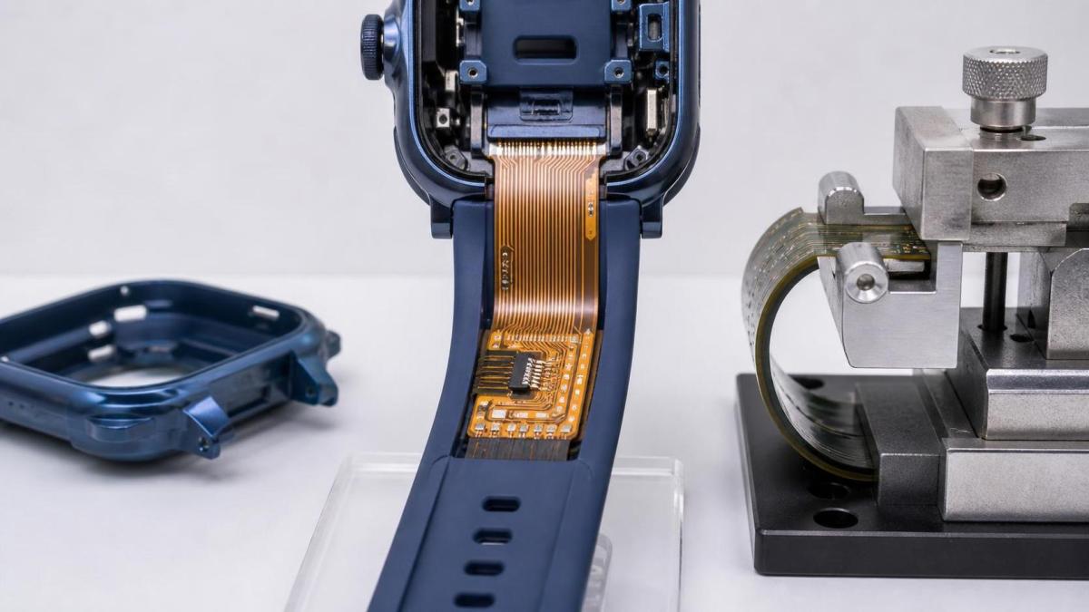
A dynamic bend is repeatedly flexed during normal use. This includes a circuit running through a watch band, a foldable sensor arm, a cable-like connection between moving wearable sections, or an electronic textile zone near a joint. Here, cycle life becomes central. A radius that is acceptable for one-time folding can be unsuitable for daily movement.
Design teams sometimes label a region “static” because users are not expected to deliberately bend it. In practice, body-worn products experience unpredictable loading: torsion when a band twists, local creasing when a device is removed, compression under clothing, and accidental over-bending during charging or cleaning. If a user can flex that area in ordinary handling, it deserves a dynamic-use assessment.
What actually fails when the FPC is bent too tightly?
The visible flex area is often blamed first, but bend-related failures can originate in several places. Understanding the failure modes helps engineers choose the right corrective action rather than simply increasing copper thickness or adding more reinforcement.
- Copper trace fatigue: Repeated tensile strain may initiate cracks, especially where traces are narrow, have abrupt direction changes, or sit far from the neutral axis.
- Cracking at plated through-holes and vias: Rigid-to-flex transitions, unsupported vias, and plated features near a bend line can concentrate stress.
- Coverlay or adhesive delamination: A stiff coverlay edge, unsuitable adhesive system, or extreme curvature may cause layers to separate over time.
- Solder-joint stress: Components should not sit in a working bend zone. Their mass and local stiffness turn bending into leverage on solder joints and pads.
- Stiffener-edge damage: Polyimide or FR-4 stiffeners are useful in connector and component areas, but their edges can become mechanical stress risers if placed too close to the flex zone.
- Shield and laminate cracking: EMI shielding films, ground layers, and other added constructions may improve electrical performance while reducing flexibility if not designed with the intended motion in mind.
Wearable failures can be frustratingly intermittent. A circuit may pass continuity testing while laid flat, then lose connection only when the wearer bends a wrist or adjusts a strap. This is why post-assembly inspection alone is not enough; electrical monitoring during controlled flexing is far more revealing.
FPC stack-up matters as much as the nominal bend radius
There is no single bend-radius ratio that safely applies to every wearable. Broad rules of thumb can provide an initial conversation, but they should not replace material-specific validation. A one-layer dynamic flex, a multilayer sensor interconnect, and a shielded flex carrying high-speed data have different mechanical realities.
Several stack-up choices influence whether an FPC can tolerate repeated bending:
Thin, ductile copper is generally friendlier to dynamic flexing
Thicker copper increases current-carrying capability but also increases bending strain at the outer surfaces. Rolled-annealed copper is commonly preferred in demanding dynamic-flex applications because its grain structure typically tolerates repeated flexing better than electrodeposited copper. The best choice still depends on current, impedance, manufacturability, and the actual motion profile.
Layer count and symmetry affect the neutral axis
Every added conductive, adhesive, dielectric, or shielding layer increases thickness and can move traces farther from the neutral axis. In a repeatedly flexed zone, minimizing unnecessary layers is often more valuable than forcing a compact but mechanically rigid construction through a tight curve. Where multiple layers are unavoidable, balanced stack-up planning can reduce uneven strain.
Coverlay design deserves close attention
Coverlay protects traces and supports insulation reliability, but it also contributes to overall stiffness. Openings, edge geometry, and adhesive selection should be reviewed around bend regions. A coverlay edge ending directly at the peak of a bend can create a local discontinuity in stiffness, encouraging strain concentration.
Trace routing can either distribute or concentrate stress
In a dynamic bend area, traces should generally cross the bend direction as directly and uniformly as possible. Sharp corners, abrupt width changes, and clustered conductors can create weak points. Staggering traces across the bend zone may improve flexibility versus placing many traces tightly together, provided signal and impedance requirements are preserved.
Where wearable design often goes wrong
The pressure to make products slimmer can turn a mechanical problem into a packaging compromise. A battery expands into the only available volume, a connector moves closer to a hinge zone, or a stiffener is extended to simplify assembly. Each choice may seem harmless in isolation. Together, they can force the FPC to bend at a radius it was never designed to endure.
Another recurring mistake is allowing the bend location to wander. A flex circuit may be designed with a generous curved path, but without guides, retention features, or strain-relief geometry, it can crease at a different point each time the device moves. The actual bend line then migrates toward a coverlay edge, a via field, or a soldered section.
Environmental exposure complicates this picture. Skin-contact wearables encounter sweat, skin oils, temperature changes, and cleaning agents. Moisture ingress or chemical stress may not cause the initial mechanical crack, but it can accelerate degradation after the insulation or copper has been strained. A long-life design must consider bending and environmental reliability together.
A practical way to set bend-radius requirements
Rather than selecting a radius from a generic chart and moving on, define the requirement from use conditions. The following questions create a more defensible design basis:
- Is the zone static, occasionally flexed, or continuously dynamic? Classify by real user behavior, not only intended assembly configuration.
- What is the smallest radius the product can impose? Consider normal wear, removal, torsion, misuse, storage, and assembly fixtures.
- How many cycles and what motion range are plausible? A small repeated bend angle may be less severe than periodic full folding, but both require testing.
- Which layers are farthest from the neutral axis? Review copper placement, shields, coverlay, and adhesive thicknesses—not just finished board thickness.
- What features lie near the bend? Move vias, pads, stiffener edges, component footprints, and abrupt trace geometry away from the active bend area wherever possible.
- What electrical functions are most sensitive? High-speed, RF, analog sensing, and power paths may need different routing and monitoring strategies.
The final requirement should be communicated to the FPC fabricator as part of the mechanical specification. “Flexible” is not a sufficient requirement. State the expected bend orientation, target radius, dynamic or static classification, expected motion, stack-up constraints, and any electrical checks required during flex testing.
How should an FPC be tested for wearable lifetime?
A meaningful reliability plan reproduces the product’s actual stress instead of applying a generic bend test with little connection to the end use. The fixture should control bend radius, angle, speed, and cycle count while continuously or periodically checking electrical continuity. For sensitive sensor or RF circuits, engineers may also monitor resistance drift, signal quality, impedance-related behavior, or functional output during movement.
Testing should include more than pristine room-temperature samples. Wearable FPCs may need evaluation after environmental conditioning, thermal cycling, humidity exposure, and assembly-level loading. The goal is not to create an unrealistic torture test; it is to expose the combination of stresses that a device may accumulate in the field.
Failure analysis is equally important. If a sample opens after flexing, cross-sectioning and microscopy can distinguish copper fatigue from adhesive separation, plating damage, or solder-joint failure. That distinction informs whether the redesign should change the bend radius, material selection, trace geometry, stiffener placement, or the housing mechanics.
Frequently asked questions
What is a safe bend radius for an FPC in a wearable device?
A safe radius depends on FPC thickness, copper type and thickness, number of layers, coverlay construction, and whether the bend is static or dynamic. Dynamic wearable applications usually require a more conservative radius than one-time installation bends. Use supplier guidance as a starting point, then verify the complete design through representative flex-cycle testing.
Can adding a stiffener improve FPC lifespan?
Yes, when it protects connector, component, or insertion areas from local flexing. No, if it pushes stress into an adjacent moving region. The stiffener should terminate outside the active bend zone, with the transition carefully evaluated for strain concentration.
Does a thicker FPC always last longer?
Not in a dynamic bend application. A thicker circuit may be more robust against handling damage, but it experiences greater surface strain at the same bend radius and can become less fatigue-tolerant. Mechanical durability comes from the full construction and routing strategy, not thickness alone.
Can an FPC be folded at a sharp crease?
A sharp crease is generally a high-risk condition unless the circuit and materials are expressly designed and qualified for that form of bending. In most wearable products, it is better to guide the flex into a controlled curve and prevent users or assembly operations from creating a fold line.
Designing for the motion people actually make
The relationship between FPC bend radius and circuit lifespan is ultimately a relationship between engineering assumptions and human behavior. Wearables live on moving bodies, in bags, under sleeves, near sweat and skin oils, and in the hands of users who will bend them in ways no CAD model fully predicts.
For engineering and procurement teams, the useful question is not simply, “Will this FPC fit?” It is, “Will this stack-up, routing pattern, and mechanical path remain electrically stable after the product has been worn as intended?” Independent benchmarking of material properties, fabrication capability, and reliability evidence can make that decision less speculative. At SiliconCore Metrics, we view these details as connected: a bend-radius target is meaningful only when it is evaluated alongside copper construction, layer symmetry, manufacturing tolerances, and realistic service conditions.
A generous, controlled bend radius is often one of the quietest design choices in a wearable—and one of the clearest signals that its lifespan was considered before the first field return made the issue visible.
Recommended News
- Flexible CircuitsHow Does FPC Bend Radius Affect Wearable Device Lifespan?How does FPC bend radius impact circuit lifespan in wearable devices? Discover design, stack-up, and testing strategies that reduce flex fatigue and boost reliability.
- Flexible CircuitsFlexible Printed Circuits IPC Standards: What Affects Reliability MostFlexible printed circuits IPC reliability depends on more than compliance. Discover what most affects flex life, process risk, and long-term performance.
- Flexible CircuitsIPC-7351C Tightens FPC Pad Tolerance to ±0.05 mmIPC-7351C tightens FPC pad tolerance to ±0.05 mm and mandates 3D validation reports. Learn how this update impacts HDI-FPC design, yield control, sourcing, and compliance.
- Flexible CircuitsHVLP Foil Lead Times Stretch as Flexible Circuit Supply Gap Reaches 63%HVLP copper foil lead times stretch to 22 weeks as the flexible circuit supply gap hits 63%. Learn how FCCL, FPC, wearable, and Q3 delivery plans may be affected.
- Flexible CircuitsHVLP Copper Foil Lead Times Extend Again, FPC Supply Gap WidensHVLP copper foil lead times extend to 22–26 weeks as the FPC supply gap widens. Learn how supplier qualification, LTA-backed sourcing, and certification shifts are reshaping Flexible Circuits procurement.
- Flexible CircuitsHVLP Copper Foil Lead Times Stretch as Flexible Circuit Material Gap WidensHVLP copper foil lead times stretch to 32 weeks as the Flexible Circuit material gap widens to 63%. See what FPC buyers, traders, and sourcing teams should monitor now.