
Flexible Printed Circuits IPC Standards: What Affects Reliability Most
DETAILS
Flexible printed circuits IPC standards are often treated as a compliance checkpoint, yet reliability is decided much earlier and tested much harder in real use. A flex circuit may pass documentation review and still fail under repeated bending, thermal cycling, or assembly stress.
That gap matters across the semiconductor and EMS supply chain, where compact packaging, tighter signal margins, and longer service life are now expected at the same time. In practice, the most dependable evaluations connect IPC requirements with material behavior, process control, and the actual mechanical duty cycle.
For organizations that rely on benchmark-driven sourcing, this is where flexible printed circuits IPC analysis becomes useful. It turns a broad standard into a sharper way to judge long-term performance, application fit, and manufacturing risk.
Why IPC compliance is only the starting point
IPC standards create a common language for design, fabrication, inspection, and acceptability. They help align suppliers, buyers, and quality teams around measurable expectations.
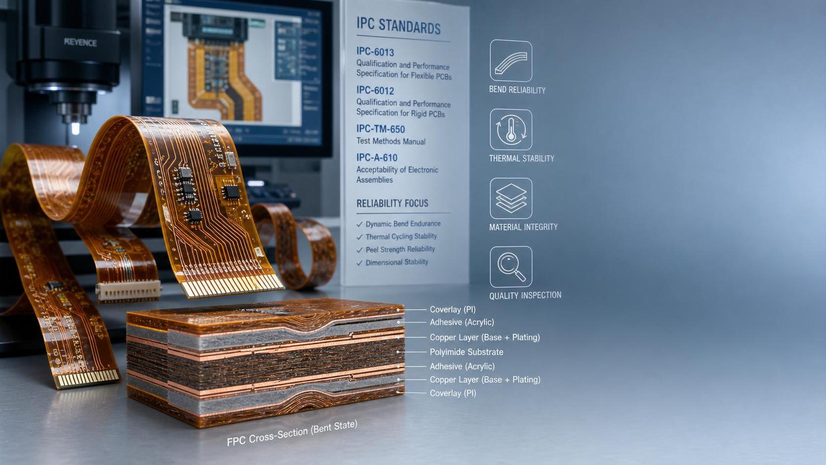
For flex and rigid-flex designs, relevant references often include IPC-2223 for design guidance and IPC-6013 for qualification and performance. These documents are essential, but they do not remove application complexity.
A circuit used in a foldable medical device, an automotive camera module, and an industrial sensor harness may all meet flexible printed circuits IPC requirements. Their reliability outlooks can still be very different.
The reason is simple. Standards define minimum structure and acceptance criteria, while field life depends on repeated stress, environmental exposure, and stack-up decisions made during design and manufacturing.
The factors that drive reliability most
When failures are traced back, a few variables appear more often than others. They interact with each other, which is why isolated data points can be misleading.
Base material and dielectric stability
Polyimide remains the dominant flex substrate because it combines thermal endurance with mechanical flexibility. Even then, not all polyimide systems behave the same under moisture, heat, or dynamic bending.
Material thickness, dielectric consistency, and dimensional stability affect both mechanical life and signal behavior. In dense layouts, slight variation can change impedance control and increase stress concentration near transitions.
Copper type and fatigue resistance
Copper fatigue is one of the most common reliability limits in dynamic flexing. Rolled annealed copper generally performs better than electrodeposited copper in repeated bend applications because its grain structure supports greater ductility.
Copper thickness also matters. Thicker copper supports current handling, but it reduces flexibility and raises the strain experienced during bending. That tradeoff must be judged against real duty cycles, not generic preferences.
Adhesive and adhesive-less constructions
Adhesive layers can simplify construction, but they may introduce weak points under heat and humidity. Adhesive flow, voiding, and mismatched expansion can reduce stability over time.
Adhesive-less laminates often deliver better dimensional control and improved high-cycle bending performance. They may cost more, but in demanding applications, the reliability return is often measurable.
Bend radius and circuit geometry
Bend radius is not a minor design note. It is one of the clearest predictors of whether a flex circuit will survive long-term movement.
A tight bend radius increases strain on copper and dielectric layers. Sharp transitions, trace stacking, vias in bend zones, and abrupt coverlay edges can amplify that stress further.
Designs that spread traces, stagger conductors, and keep plated through holes away from dynamic bend areas usually show better life in testing and in service.
Where reliability problems usually begin
Most failures do not come from a single catastrophic mistake. They develop from cumulative weakness across design choices, fabrication tolerances, and assembly handling.
This is why flexible printed circuits IPC review should not stop at certificates. Process capability evidence, cross-section data, and life-test results are often more revealing than a compliance claim alone.
Industry pressure is changing what counts as acceptable
Several market shifts are increasing scrutiny. Electronics are getting thinner, operating temperatures are less forgiving, and interconnect density is rising across consumer, automotive, aerospace, industrial, and medical platforms.
That means flexible printed circuits IPC decisions now sit closer to signal integrity, thermal management, and system uptime than before. A flex circuit is no longer just a space-saving connector replacement.
In many assemblies, it becomes a structural and electrical reliability component. Small deviations in dielectric performance, trace adhesion, or bend endurance can influence the entire product qualification path.
This is also where independent benchmarking adds value. Organizations such as SiliconCore Metrics frame reliability through measurable fabrication data, compliance evidence, and comparative analysis across the broader EMS supply chain.
How to evaluate flexible printed circuits IPC in practical terms
A useful evaluation model connects standards with application stress. The aim is not to gather more paperwork. It is to reduce uncertainty before qualification or supplier selection moves forward.
Look beyond pass or fail language
Ask how the circuit was tested, not only whether it passed. Dynamic flex life, thermal shock, humidity exposure, and soldering survivability reveal different failure mechanisms.
A static bend design may not need the same evidence as a high-cycle hinge application. The test profile should resemble actual use conditions as closely as possible.
Review stack-up decisions as reliability choices
- Check whether copper type matches the expected bending profile.
- Confirm that coverlay, stiffeners, and adhesive systems suit the thermal environment.
- Examine whether vias or component pads intrude into bend-sensitive regions.
- Compare conductor thickness with both current demand and required flex life.
Use tolerance data to estimate process maturity
Registration accuracy, coverlay alignment, drilled feature consistency, and plating variation often indicate whether a supplier can repeat the same result at volume.
For flexible printed circuits IPC work, repeatability may matter more than a single sample that looks excellent. Reliability programs fail when qualification data cannot be reproduced in production lots.
Typical application contexts and what changes between them
Not every flex circuit carries the same risk profile. Reliability priorities shift depending on whether the design is static, semi-dynamic, or continuously moving.
This is why flexible printed circuits IPC interpretation should stay application-specific. The same standard framework supports all of these cases, but the judgment criteria cannot be identical.
A more useful next step
The most reliable path is to treat flexible printed circuits IPC review as part of a broader evidence set. Combine standard compliance with bend-life data, material disclosure, tolerance capability, and cross-section verification.
Then map those findings to the real product environment: motion profile, temperature range, assembly method, expected service life, and acceptable failure rate. That approach makes qualification decisions more defensible.
Where uncertainty remains, comparative benchmarking is usually more valuable than generic claims. A structured review of stack-up, process discipline, and long-term test evidence will show which designs are merely compliant and which are genuinely robust.
Recommended News
- Flexible CircuitsHow Does FPC Bend Radius Affect Wearable Device Lifespan?How does FPC bend radius impact circuit lifespan in wearable devices? Discover design, stack-up, and testing strategies that reduce flex fatigue and boost reliability.
- Flexible CircuitsFlexible Printed Circuits IPC Standards: What Affects Reliability MostFlexible printed circuits IPC reliability depends on more than compliance. Discover what most affects flex life, process risk, and long-term performance.
- Flexible CircuitsIPC-7351C Tightens FPC Pad Tolerance to ±0.05 mmIPC-7351C tightens FPC pad tolerance to ±0.05 mm and mandates 3D validation reports. Learn how this update impacts HDI-FPC design, yield control, sourcing, and compliance.
- Flexible CircuitsHVLP Foil Lead Times Stretch as Flexible Circuit Supply Gap Reaches 63%HVLP copper foil lead times stretch to 22 weeks as the flexible circuit supply gap hits 63%. Learn how FCCL, FPC, wearable, and Q3 delivery plans may be affected.
- Flexible CircuitsHVLP Copper Foil Lead Times Extend Again, FPC Supply Gap WidensHVLP copper foil lead times extend to 22–26 weeks as the FPC supply gap widens. Learn how supplier qualification, LTA-backed sourcing, and certification shifts are reshaping Flexible Circuits procurement.
- Flexible CircuitsHVLP Copper Foil Lead Times Stretch as Flexible Circuit Material Gap WidensHVLP copper foil lead times stretch to 32 weeks as the Flexible Circuit material gap widens to 63%. See what FPC buyers, traders, and sourcing teams should monitor now.