
Precision capacitors guide to choosing the right tolerance
DETAILS
Precision Capacitors Guide to Choosing the Right Tolerance
Selecting a precision capacitor is rarely as simple as matching a capacitance value and choosing the tightest tolerance available. A 10 nF part marked at ±1% may be an excellent fit for one circuit and a poor choice for another if its capacitance shifts under DC bias, temperature, frequency, mechanical stress, or long operating time. In high-performance electronics, the usable capacitance in the assembled product matters more than the number printed on the purchasing specification.
That distinction becomes critical in clock circuits, RF matching networks, precision filters, sample-and-hold stages, timing paths, isolated power supplies, and automotive or industrial control systems exposed to large temperature swings. The component may pass incoming inspection at room temperature yet still move outside the circuit’s acceptable range after reflow or under real electrical loading.
This precision capacitors guide focuses on the practical tolerance questions that should be resolved before a part is approved: what the tolerance actually controls, which dielectric behavior dominates the application, how to read supplier data beyond the front-page specification, and when a tighter tolerance is worth paying for.
Tolerance is only one part of the capacitance budget
A stated capacitance tolerance normally describes the allowed variation from nominal value under defined test conditions. Those conditions are important. They may specify measurement frequency, AC test level, temperature, and sometimes preconditioning requirements. If the circuit operates far from those conditions, the label alone does not predict in-circuit behavior.
A useful qualification exercise is to treat nominal tolerance as one term in a broader capacitance budget. The final budget may also include temperature coefficient, DC-bias behavior, aging, voltage coefficient, frequency response, soldering effects, and measurement uncertainty. For a stable dielectric, initial tolerance may be the largest term. For a high-capacitance multilayer ceramic capacitor used near rated voltage, DC-bias loss can be much more consequential than whether the ordered tolerance is ±10% or ±5%.
This is where teams often over-specify. They purchase a narrower initial tolerance because the schematic calculation looks tight, while the chosen dielectric still moves substantially in actual service. The result is a more expensive bill of materials without a genuinely more predictable circuit.
The reverse error is also common: a broad-tolerance capacitor is selected because the nominal value appears noncritical, but it sits inside a compensation loop or timing network where accumulated variation creates difficult-to-debug field behavior. The right decision comes from understanding sensitivity at the circuit level, not from treating tolerance as a general quality grade.
Start with the circuit function, not the capacitor family
Before comparing distributors or manufacturer part numbers, identify what the capacitor is doing. A decoupling capacitor, a resonant element, and an RC timing capacitor can share the same nominal value while requiring completely different tolerance behavior.
For example, an MLCC used as bulk local decoupling may be entirely appropriate with a moderate initial tolerance if the design has been simulated using worst-case effective capacitance. In a low-drift integrator or a narrow-band filter, that same capacitor technology may create avoidable uncertainty. The application dictates whether stability, capacitance density, low loss, small size, voltage rating, or cost should lead the decision.
Dielectric choice usually decides the real tolerance
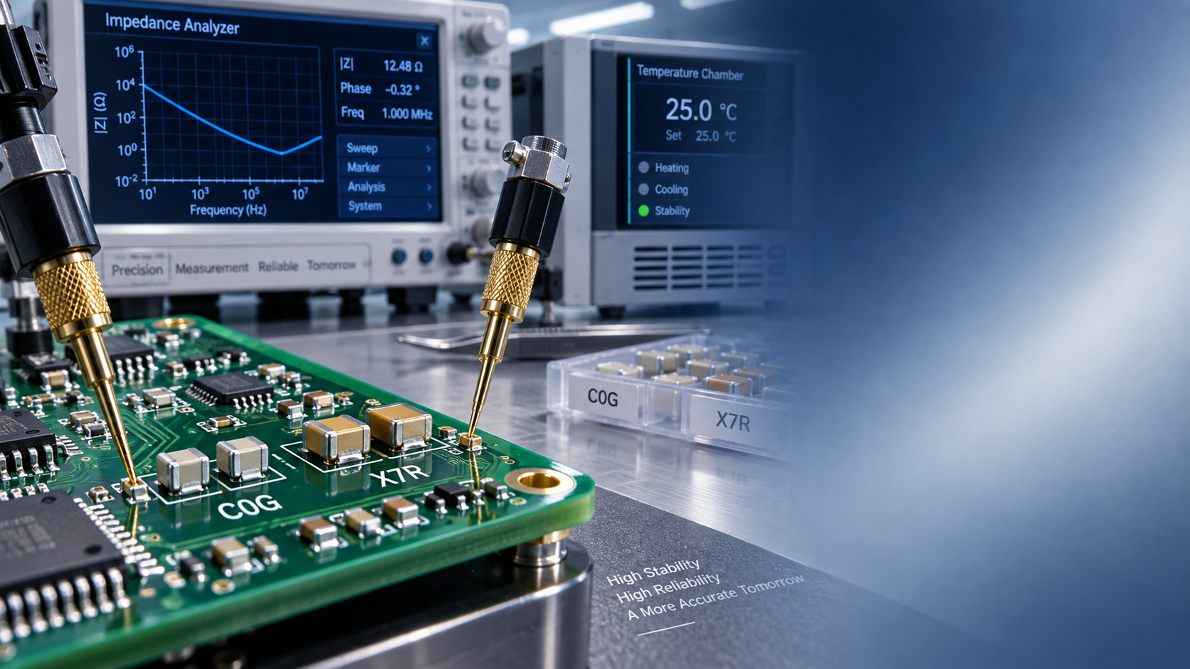
The dielectric is not a secondary detail. It largely determines whether a capacitor remains close to its nominal value over time and operating conditions. Ceramic capacitors are often grouped into more stable Class 1 materials and higher-capacitance Class 2 materials. Class 1 dielectrics, including C0G/NP0 types, are commonly selected where predictable capacitance, low loss, and stable high-frequency behavior matter. They are frequently considered for precision analog, RF, and timing functions, although available capacitance and package options may be more limited.
Class 2 ceramic dielectrics such as X7R are widely used because they provide substantial capacitance in compact packages. They can be very effective in power and general-purpose designs, but their actual capacitance may depend materially on applied DC voltage, temperature, and age. A tolerance code on an X7R part should therefore never be interpreted as a guarantee that the same percentage applies throughout the product’s operating envelope.
Film capacitors can offer favorable stability and low dielectric absorption in many precision and pulse applications, but size, leaded construction, cost, and mounting constraints may rule them out. Tantalum and aluminum electrolytic capacitors address other needs, particularly energy storage and bulk filtering, yet their leakage, ESR, lifetime characteristics, and polarity requirements need separate analysis. “Precision capacitor” is not a single technology category; it is a performance requirement that must be tied to a circuit function.
A practical rule is simple: if the design margin depends on capacitance staying tightly controlled, begin with the most stable dielectric family that is feasible for the required value, voltage, size, and frequency. Do not begin with the smallest package or lowest unit price and try to recover precision through a narrow tolerance code.
Read the datasheet for conditions, curves, and omissions
A credible evaluation goes beyond the ordering table. The first question is how capacitance is measured. A supplier may state the nominal value at a particular test frequency and AC signal level. For high-value capacitors, measurements at different frequencies can produce a meaningfully different result. If the circuit operates at switching frequency, RF frequency, or a very low analog frequency, the test method should be relevant to that use case.
For ceramic parts, look specifically for capacitance-versus-DC-bias curves, capacitance-versus-temperature behavior, and aging information. If the documentation provides only a generic family curve, treat it as directional rather than definitive. Behavior can vary with capacitance value, voltage rating, case size, and internal construction. A 0402 component and a larger 1210 component with the same dielectric designation should not automatically be treated as interchangeable from a stability standpoint.
Voltage rating deserves careful interpretation as well. A capacitor rated for a given voltage is not necessarily suitable for precision service at that voltage. Electrical rating, lifetime expectation, and acceptable capacitance change are separate decisions. Derating may improve reliability and stabilize behavior, but the appropriate margin must come from the component data, the expected transient profile, and the equipment environment rather than a universal percentage rule.
Also review dissipation factor, ESR, ESL, insulation resistance, leakage current, and self-resonant frequency where relevant. In an RF path, a capacitor can meet its nominal capacitance tolerance and still fail the design because its parasitics move the impedance or resonant point. In a high-impedance analog node, leakage and dielectric absorption can matter more than small differences in initial capacitance.
Manufacturing and assembly can change what was qualified
Component selection does not end at the datasheet. In multilayer ceramic capacitors, board flexure, poor land-pattern design, excessive solder volume, and depanelization stress can create cracks that are difficult to detect visually. A capacitor may remain electrically functional during production test but develop insulation or reliability problems later. This risk is particularly relevant for larger ceramic packages and boards that experience mechanical loading.
Reflow exposure, cleaning chemistry, conformal coating, humidity, vibration, and thermal cycling should be considered as part of the qualification environment. For an assembly intended to meet demanding reliability expectations, component documentation alone is not enough. The PCB stack-up, pad geometry, placement process, solder profile, and inspection method all influence the final result.
This is why independent manufacturing intelligence can be useful during evaluation. SiliconCore Metrics examines the broader interaction between passive components, PCB materials, SMT placement precision, and long-term behavior under environmental stress. For teams comparing suppliers across regions, standardized component and assembly evidence can be more useful than relying on nominally similar part descriptions. The goal is not to make a component look better on paper; it is to establish whether its behavior remains controlled in the finished system.
Build a qualification plan around worst-case use, not typical samples
A sensible qualification plan begins with a circuit-level acceptance range. Define the minimum and maximum capacitance the function can tolerate, then map that range against real operating temperature, applied voltage, frequency, aging expectation, and manufacturing conditions. This turns an abstract tolerance discussion into a traceable engineering decision.
For a new source or an alternate manufacturer, request the documentation needed to verify the actual ordering code, dielectric, voltage rating, package, termination type, lot traceability approach, and applicable reliability information. Where the capacitor is safety- or mission-critical, confirm that the released manufacturer part number matches the qualified construction. A similar-looking substitute can have different internal layers, electrode materials, or process controls.
Bench testing should mirror the real concern. That may mean measuring capacitance under DC bias, characterizing impedance across frequency, checking drift through the expected temperature range, or evaluating samples after reflow and environmental exposure. For a high-volume design, variation across lots can matter as much as the average result from a small sample set. Procurement and engineering should agree in advance on what variation is acceptable and what change-notification process is required.
This is especially relevant in a supply chain where availability pressure encourages second-source approval. An approved alternate should be qualified against the application’s electrical and mechanical requirements, not merely against nominal capacitance, voltage rating, and package footprint. Equivalent is a circuit-level conclusion, not a catalog description.
When should you pay for a tighter initial tolerance?
Tighter tolerance is justified when initial value spread directly affects a controlled outcome and other sources of drift are already low. Typical examples include precision RC timing, calibrated analog filtering, frequency-setting networks, and matching functions where adjustment is unavailable or undesirable. In these situations, a stable dielectric and a narrow tolerance work together.
It is less valuable when the design is dominated by DC-bias reduction, broad thermal variation, PCB parasitics, or a control loop that already accommodates capacitance movement. A moderately tolerant component with well-understood behavior may be safer than a tight-tolerance part selected from an unsuitable dielectric family.
The strongest capacitor specifications state the required effective performance, not just a nominal value and a tolerance letter. They define the operating conditions, permitted drift, critical electrical parameters, qualification evidence, and substitution controls. That approach gives engineering a more defensible design margin and gives sourcing a clearer basis for comparing manufacturers.
The final choice should answer one practical question: under the worst credible combination of voltage, temperature, frequency, assembly stress, and service life, will this capacitor still keep the circuit inside its limits? If the answer depends only on the value printed on the label, the evaluation is not finished.
Recommended News
- Precision CapacitorsPrecision capacitors guide to choosing the right tolerancePrecision capacitors guide to choosing the right tolerance: compare dielectric stability, DC-bias effects, temperature drift, and qualification factors for reliable designs.
- Precision CapacitorsHow to verify RoHS compliance for lead free passive componentsLead free passive components: learn how to verify RoHS compliance with part-specific declarations, exemption checks, lot traceability, and targeted testing.
- Precision CapacitorsEU EN 62368-3:2026 Takes Effect for Precision CapacitorsEU EN 62368-3:2026 takes effect for precision capacitors, reshaping EU compliance for AV and IT equipment. Learn Annex D report requirements, thermal runaway risks, and supply chain impacts.
- Precision CapacitorsHow Passive Component Category Intelligence Improves Capacitor Sourcing DecisionsPassive component category intelligence helps buyers make smarter capacitor sourcing decisions by reducing risk, controlling cost, and approving truly usable alternates faster.
- Precision CapacitorsAEC-Q200 Specification: Key Tests and Pass CriteriaAEC Q200 specification explained: discover key tests, pass criteria, and practical evaluation tips to compare passive components, reduce sourcing risk, and improve reliability decisions.
- Precision CapacitorsPassive Component Technology Intelligence: Key Signals for 2026 Sourcing DecisionsPassive component technology intelligence reveals the 2026 sourcing signals that impact reliability, cost, and supply continuity—helping buyers reduce risk and make smarter decisions.