
When does FR4 PCB assembly need tighter reflow temperature control?
DETAILS
When Does FR4 PCB Assembly Need Tighter Reflow Temperature Control?
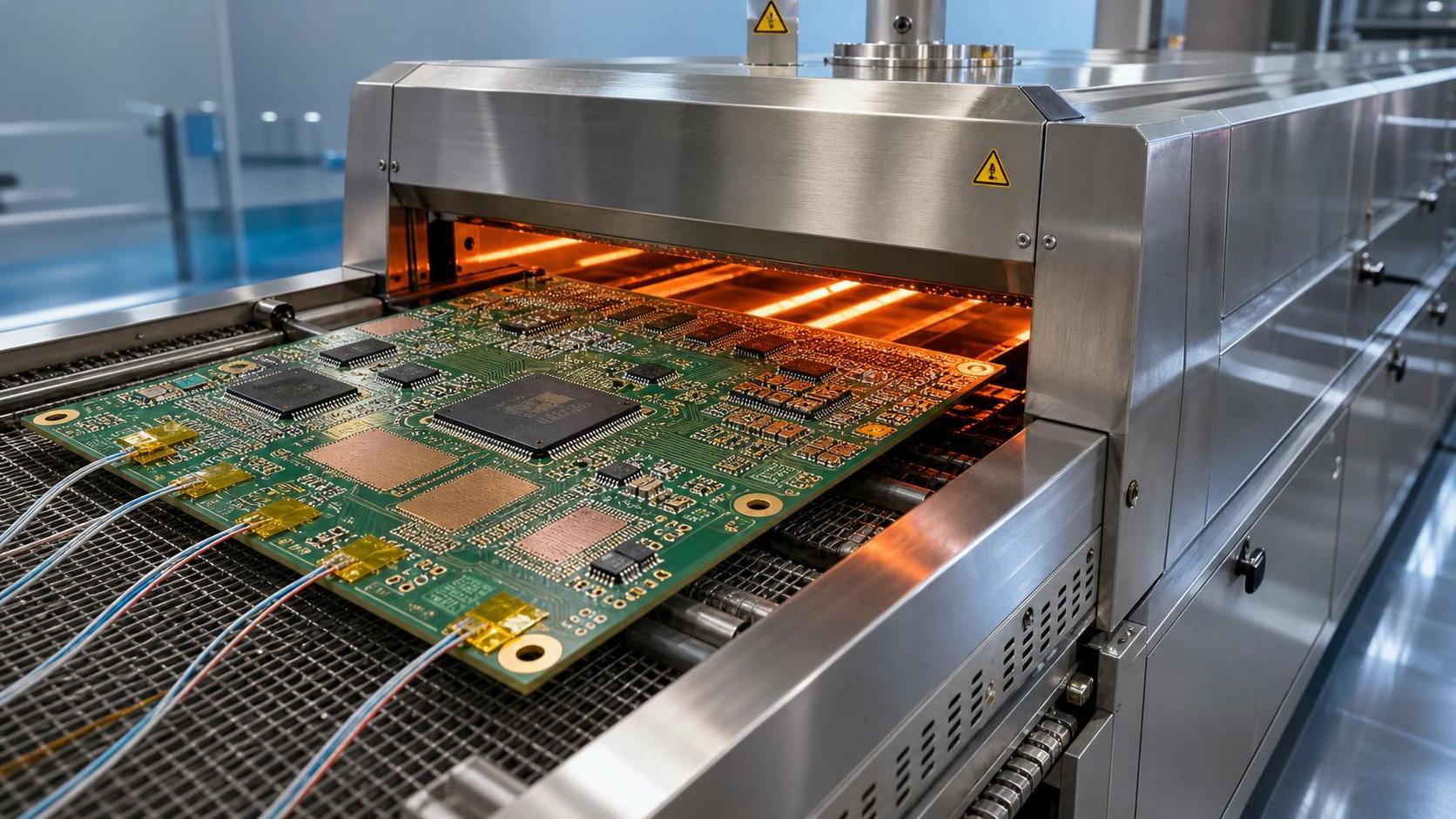
FR4 PCB assembly needs tighter reflow temperature control when board complexity, component density, copper imbalance, or reliability requirements narrow the acceptable process window. For a simple, low-density consumer board, a broadly qualified oven recipe may provide adequate soldering performance. That same approach becomes risky when a design contains fine-pitch packages, large thermal pads, heavy copper planes, high-layer-count stackups, moisture-sensitive devices, or laminate systems operating close to their thermal limits.
The issue is not merely whether the oven reaches a specified peak temperature. A reflow profile is a time-and-temperature history experienced differently by every location on the assembly. The hottest and coolest points may be separated by substantial thermal mass, copper distribution, shielding, component geometry, and conveyor orientation. If the process window is wide, that variation may be tolerable. If the window is narrow, profile control becomes a reliability requirement rather than a production refinement.
For technical evaluators, the practical question is: when does a standard reflow setup cease to be enough? The answer usually emerges from the interaction of laminate behavior, component specifications, solder alloy requirements, assembly geometry, and the intended service environment.
FR4 Is a Material Family, Not a Single Thermal Limit
“FR4” is often treated as though it describes one consistent material with one reflow tolerance. It does not. FR4 identifies a broad family of flame-retardant glass-reinforced epoxy laminates. Actual performance depends on the specific resin system, glass style, copper construction, cured thickness, decomposition characteristics, and the fabricator’s process control.
The glass transition temperature, commonly referred to as Tg, is relevant because the resin changes mechanical behavior as it approaches and exceeds that transition. Above Tg, the laminate generally becomes more compliant and its coefficient of thermal expansion in the Z-axis increases. This does not mean that a board immediately fails when its reflow peak exceeds Tg; most assemblies do. It means that repeated or poorly controlled exposure above Tg can increase stress on plated through-holes, vias, resin interfaces, and copper features.
A meaningful evaluation also considers thermal decomposition behavior, time above critical temperatures, and Z-axis expansion. A high-Tg laminate may offer a larger margin in one area while still requiring careful review of its full datasheet and compatibility with the intended assembly cycle. In particular, technical teams should avoid approving a material solely because a quoted Tg appears suitable for lead-free soldering.
Tighter control is justified when the selected laminate has limited thermal margin for the planned number of reflow excursions, including top-side and bottom-side assembly, rework, selective soldering exposure, or later repair operations. A board that survives one controlled pass may not behave the same way after several thermal cycles.
Lead-Free Assembly Narrows the Margin
The move from traditional tin-lead soldering to common lead-free alloys raised reflow temperatures and made thermal profiling more consequential. The exact acceptable peak, soak behavior, ramp rate, and time above liquidus must be taken from the solder paste supplier and the component manufacturer’s allowed profile. There is no universal oven recipe that can safely substitute for those documents.
Lead-free reflow creates a familiar balancing problem. Too little energy can leave insufficient wetting, incomplete solder coalescence, void-related concerns under thermal pads, or cold-joint-like defects. Too much energy can increase intermetallic growth, stress sensitive packages, discolor board finishes, accelerate laminate damage, and promote warpage. The process engineer is not simply trying to “hit peak.” The task is to ensure that the coldest solder joint receives enough energy while the hottest component and board area remain within their approved limits.
This balance becomes much harder on assemblies containing BGAs, bottom-terminated components, large QFNs, power modules, metal-shielded devices, or connectors with substantial thermal mass. In these cases, a profile that looks acceptable at a convenient board-edge thermocouple can conceal an underheated central thermal pad or an overheated small package near a dense copper region.
Board Construction Often Determines Whether Profiling Must Be More Precise
High-layer-count and mixed-technology boards deserve particular attention. More layers do not automatically create a reflow problem, but they frequently introduce uneven heat absorption and heat dissipation. Internal ground planes, thick copper layers, buried structures, large copper pours, and localized thermal relief patterns all affect how rapidly different regions heat and cool.
Copper imbalance is one of the most common reasons to tighten reflow control. A compact RF section with extensive grounding may heat very differently from an adjacent low-copper digital area. The same imbalance can contribute to board bow and twist during reflow, particularly on thin panels or long, narrow boards. Warpage matters because it can disturb solder joint formation, especially beneath area-array packages where the joints cannot be visually inspected after assembly.
Thermal profiling should therefore use measurement locations that represent actual risk, not merely convenient locations. A useful profile commonly includes a low-thermal-mass area, a high-thermal-mass area, a component identified as temperature-sensitive, and a representative large thermal-pad or area-array location. The precise selection depends on the design. A single thermocouple location rarely characterizes a complex assembly adequately.
Conditions that normally justify a narrower process window
- Fine-pitch BGAs, chip-scale packages, bottom-terminated components, or other hidden-joint devices.
- Large copper planes, heavy copper layers, thick boards, or strongly asymmetric stackups.
- Thin boards and panel formats with a known tendency toward bow, twist, or conveyor-related distortion.
- High-Tg, halogen-free, low-loss, high-speed, or otherwise specialized laminate systems that require material-specific review.
- Assemblies with several reflow passes, significant rework exposure, or a combination of reflow and other high-temperature operations.
- IPC Class 3-oriented applications, safety-critical hardware, high-vibration systems, or equipment expected to experience demanding thermal cycling.
- Components subject to moisture sensitivity classification, package warpage limits, or manufacturer-defined reflow restrictions.
Moisture Changes the Risk Calculation
Moisture is often underestimated because a board can appear normal before it enters the oven. FR4 absorbs moisture to some degree, and component packages can also absorb moisture during storage and handling. During reflow, absorbed moisture turns to vapor and expands rapidly. Depending on the material condition and thermal exposure, the result can include delamination, measling, internal cracking, pad lifting, package cracking, or reduced long-term reliability.
Component handling should follow the applicable manufacturer instructions and recognized moisture sensitivity practices, including IPC/JEDEC J-STD-020 where relevant. Board-level moisture control also needs documented handling rules when assemblies are particularly demanding. Baking is not a universal corrective action: it must be compatible with the board finish, components already installed, adhesive materials, labels, and the supplier’s recommendations.
Tighter reflow temperature control cannot compensate for uncontrolled moisture exposure, but it can prevent an already narrow condition from becoming destructive. A steep ramp, excessive peak, or unnecessary time at elevated temperature may turn latent moisture risk into visible damage.
Component Limits Must Govern the Recipe
The board is only one part of the thermal system. Assemblies frequently include parts with very different allowable profiles: ceramic capacitors, plastic connectors, oscillators, LEDs, sensors, power inductors, shield cans, and semiconductor packages. A reflow profile acceptable for the laminate may exceed the limit of a connector housing or create unacceptable package warpage in a large BGA.
A practical hierarchy is to begin with approved component and solder-paste requirements, then test whether the PCB construction can support that window across the actual board. If the coldest critical joint cannot meet soldering requirements without overheating another location, the answer is not automatically a hotter oven. The design, placement pattern, stencil strategy, solder alloy, board material, panel support, or assembly sequence may need review.
This is also why engineering teams should distinguish between a nominal reflow profile and a validated production profile. The nominal profile comes from materials and component documentation. The validated profile demonstrates, on the real assembly and real production equipment, that the required limits are met at relevant locations with acceptable repeatability.
What Good Verification Looks Like
For complex FR4 PCB assembly, verification should be treated as a controlled measurement activity rather than an occasional setup check. IPC-7530 provides recognized guidance on temperature profiling for mass soldering processes. Its value is not that it supplies one fixed recipe, but that it reinforces disciplined profiling, representative measurement selection, and process documentation.
A robust verification plan usually records the oven configuration, conveyor speed, thermocouple attachment method, board orientation, paste type, panel condition, and measured thermal response at designated locations. When the product has tight reliability requirements, teams may also connect reflow evidence to X-ray inspection, solder-joint quality criteria, warpage assessment, microsection analysis where justified, and environmental qualification plans. The appropriate acceptance method should be tied to the product specification and applicable IPC workmanship requirements, rather than inferred from appearance alone.
Common Misjudgments in FR4 Reflow Decisions
One common mistake is to assume that higher-Tg FR4 eliminates reflow concern. It may improve margin, but copper balance, package sensitivity, moisture, and cumulative exposure remain relevant. Another is to rely on a profile created for a similar-looking board. Similar dimensions do not guarantee similar thermal behavior; a change in copper distribution, package mix, or panel tooling can alter the result.
It is also risky to validate only the first article under unusually favorable conditions. Oven loading, maintenance state, ambient conditions, conveyor stability, and board condition can influence repeatability. A technically sound process does not require constant overreaction to minor variation, but it does require defined limits and a method for responding when those limits are exceeded.
A Better Basis for Technical Evaluation
The need for tighter temperature control should be decided before volume production, ideally while the material stackup, package selection, and assembly route can still be adjusted. Start with the laminate datasheet, solder-paste guidance, component reflow limits, expected number of thermal exposures, copper distribution, and service reliability requirement. Then require a measured profile on the intended board configuration rather than accepting an oven setting as proof of compliance.
This is the type of comparison work that benefits from independent manufacturing data. SiliconCore Metrics examines PCB dielectric behavior, SMT precision, component reliability, and thermal packaging through standardized technical reporting for the global electronics supply chain. For evaluators comparing material declarations or EMS process capability, the most useful evidence is specific: stackup information, profile records, component constraints, inspection methods, and documented controls for the actual assembly route.
FR4 PCB assembly does not require highly restrictive reflow control simply because it is called FR4. It requires it when the design leaves little room for thermal variation. Once hidden joints, uneven thermal mass, moisture-sensitive materials, multiple heat cycles, or high-reliability obligations enter the picture, a carefully measured and maintained profile becomes part of the product’s engineering assurance—not just an SMT line setting.
Recommended News
- Reflow SolderingHow to compare thermal profiles for reflow process benchmarkingImprove reflow process benchmarking by comparing thermal profiles, process windows, and repeatability. Discover how to evaluate ovens and suppliers with reliable, auditable data.
- Reflow SolderingHow thermal cycling reliability testing reveals solder joint fatigueThermal cycling reliability testing reveals solder joint fatigue through CTE mismatch, crack monitoring, and failure analysis—learn how to build more reliable electronics.
- Reflow SolderingHow automotive PCB assembly processes prevent solder joint failuresPCB assembly process automotive controls help prevent solder joint failures through DFM, paste inspection, precise reflow profiling, and risk-based validation. Learn proven reliability practices.
- Reflow SolderingWhat SMT process capability evidence is needed for AEC-Q100 projects?SMT process capability AEC Q100 evidence: learn the essential controls for reflow, MSL, solder-joint inspection, traceability, and automotive release.
- Reflow SolderingWhen does FR4 PCB assembly need tighter reflow temperature control?FR4 PCB assembly needs tighter reflow control when thermal mass, fine-pitch components, moisture, and reliability demands narrow the process window. Learn key profiling factors.
- Reflow SolderingWhat BGA defects reveal weak SMT process capabilitySMT process capability BGA insights: learn how BGA defects expose weak printing, placement, reflow, and inspection control—and what they mean for reliability, audits, and supplier risk.