
How High Reliability Reflow Soldering Reduces Voids and Thermal Fatigue
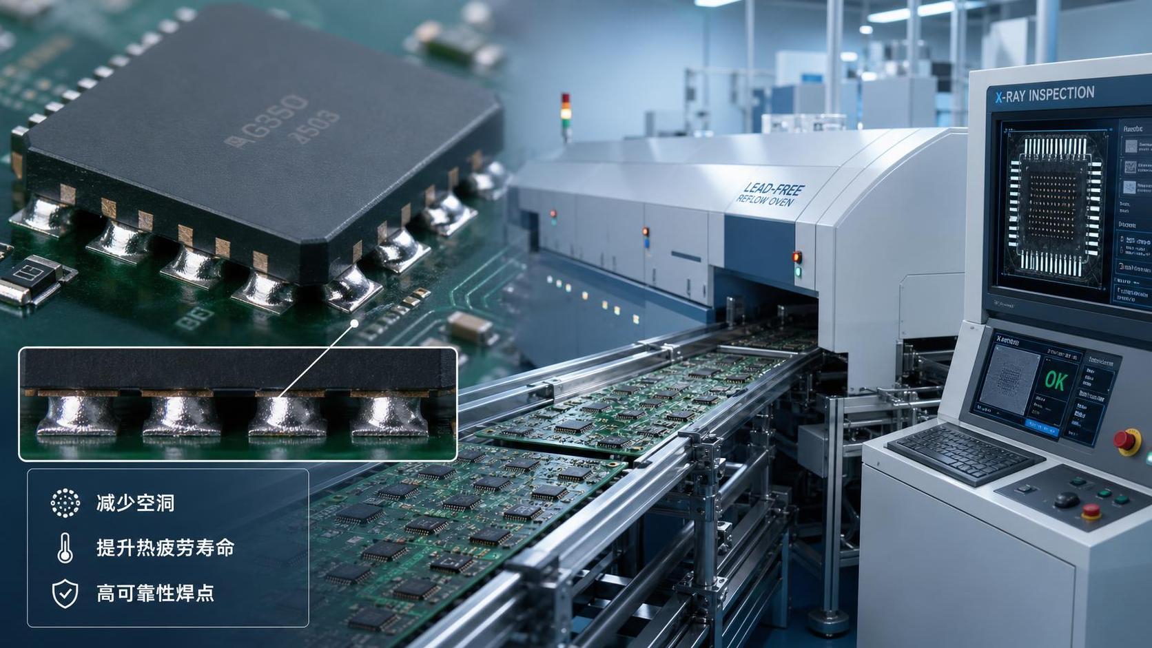
DETAILS
Why the Reflow Profile Matters More Than Many Buyers Assume
In high-reliability electronics, voiding and thermal fatigue are rarely separate problems. They are usually two expressions of the same underlying issue: the solder joint did not form, solidify, or age under conditions that support long-term mechanical and thermal stability. That is why high reliability reflow soldering should not be treated as a routine SMT setting. It is a process discipline that determines whether an apparently acceptable joint will still perform after repeated power cycling, field temperature swings, and sustained thermal load.
This distinction matters because many assemblies pass initial inspection while still carrying latent reliability risk. X-ray may show a void pattern that falls within an internal acceptance rule, and AOI may see nothing unusual at all. Yet under thermal cycling, the same joint can concentrate stress around gas pockets, intermetallic boundaries, or uneven wetting zones. In practical terms, the reflow profile is shaping both the immediate metallurgy of the joint and its future failure path.
For technical evaluators, the phrase usually refers to a controlled reflow strategy designed to reduce solder voids, limit process-induced defects, and produce joints that retain electrical and mechanical integrity across demanding service conditions. It is common in sectors where IPC-Class 3 expectations, mission-critical uptime, or harsh-environment exposure make process variation expensive.
Voids Are Not Just Cosmetic Defects
A void is a gas-filled cavity trapped in the solder joint during reflow. The mechanism is straightforward in principle but messy in production. Flux volatiles, surface contamination, paste chemistry, pad finish, component geometry, stencil design, and thermal ramp behavior all influence whether gases escape before the solder solidifies. In bottom-terminated components, power packages, thermal pads, and large ground-connected features, that escape path is often restricted. The result is a joint that may be electrically continuous but thermally and mechanically compromised.
The reliability concern depends on where the voids are, how large they are, and what the joint is expected to do. A scattered pattern of small voids in a noncritical connection is different from a large central void under a thermal pad in a power device. The first may have little practical effect; the second can raise thermal resistance, create localized hot spots, and intensify strain during thermal expansion and contraction. That is why experienced manufacturers do not evaluate voiding only by percentage area. They also look at location, joint function, package style, and failure consequence.
One common misunderstanding is that void reduction is solved by simply increasing peak temperature. Sometimes a hotter profile can help outgas the assembly more effectively. It can also damage flux behavior, accelerate oxidation, overstress moisture-sensitive components, or create excessive intermetallic growth. In other words, more heat is not automatically better reliability.
How Reflow Influences Thermal Fatigue
Thermal fatigue is the gradual cracking or degradation of a solder joint under repeated temperature change. Every cycle introduces expansion mismatch between the component, solder, PCB laminate, copper structure, and sometimes the heat sink or enclosure. If the joint geometry is inconsistent, if voids interrupt load transfer, or if the microstructure formed during reflow is poorly balanced, fatigue damage accumulates faster.
This is where high reliability reflow soldering becomes more than profile compliance. The process has to generate uniform wetting, stable collapse, and appropriate time above liquidus without pushing the assembly into unnecessary thermal stress. A poor profile can leave cold zones, incomplete coalescence, head-in-pillow risk in area-array packages, or irregular intermetallic layers. A better profile tends to reduce those gradients and produce joints with more predictable strain distribution during service.
The relationship is not linear. Low voiding alone does not guarantee long fatigue life, and a joint with moderate voiding is not automatically unreliable. Service temperature range, dwell time, CTE mismatch, package size, alloy selection, and board thickness all matter. The evaluation has to stay tied to the actual application rather than a single universal defect threshold.
What a High-Reliability Reflow Strategy Usually Includes
In production review, the strongest signal is not a supplier claiming “optimized reflow.” It is whether the process window is characterized and defended with engineering logic. A high-reliability approach usually includes control over several linked variables:
None of these variables can be judged in isolation. A profile that works for fine-pitch logic devices may not control voiding in a large thermal pad package, especially on heavy copper boards or assemblies with strong thermal imbalance. That is why robust EMS providers segment recipes by board design, mass distribution, and package family instead of forcing one profile across unrelated products.
The Industry Context: Inspection Is Necessary, but It Comes Late
A recurring procurement mistake is to evaluate solder reliability through post-process images alone. X-ray remains essential, especially for BTCs, QFNs, LGAs, and power components, but it is still a lagging indicator. By the time voiding is visible, the quality of stencil design, paste storage control, board finish condition, profile tuning, and oven stability has already been expressed in the joint.
That is why engineering reviews should ask process questions before asking for defect photos. How is the thermal profile verified across the board? How often is the oven characterized? Are void criteria differentiated by package type and thermal function? Is there a documented response when new laminate stacks or copper weights shift heat absorption? A manufacturer that can answer these questions clearly is usually in a stronger position than one presenting attractive defect snapshots without process context.
For organizations such as SiliconCore Metrics, this is exactly where independent benchmarking becomes useful. Reflow quality is often discussed as if it were a fixed capability, but in reality it is a measurable process maturity issue tied to equipment control, profile discipline, and data transparency. The more complex the assembly, the less value there is in generic claims.
Standards Help, but They Do Not Replace Engineering Judgment
Technical evaluators often look for a single standard that defines acceptable voiding and long-term solder reliability across all use cases. That is not how the field works. IPC standards, component maker guidance, internal customer specifications, and qualification test methods all contribute, but acceptance still depends on assembly type and mission profile. IPC-Class 3 can set the seriousness of workmanship expectations; it does not remove the need to interpret thermal pad function, current load, or service temperature exposure.
The same caution applies to thermal cycling data. Results from one package family, solder alloy, or board construction should not be generalized too aggressively. Reliability testing is highly sensitive to geometry and stress conditions. A supplier citing “passed thermal cycling” without clarifying the test setup is giving only partial information.
What to Look for When Comparing Manufacturing Partners
When the application has real field-risk exposure, the most useful evaluation points are specific. Ask whether the supplier profiles representative worst-case boards, not just nominal builds. Ask how they manage reflow across mixed thermal masses. Ask whether void analysis is linked to package function and whether corrective action includes stencil aperture changes, paste evaluation, and atmosphere review rather than profile changes alone.
Also pay attention to how they speak about tradeoffs. Reliable manufacturers rarely promise zero voids. They explain what level is practical for a given package, what control methods they use, and how they validate that the finished joint is fit for the product’s thermal and mechanical duty. That kind of answer reflects process ownership.
In the end, high reliability reflow soldering is best understood as a controlled balance: enough thermal energy to create a sound joint, enough process discipline to let gases escape and wetting complete, and enough data to prove the result is repeatable. For technical evaluators, that balance is the real criterion. Not whether the reflow profile looks textbook on paper, but whether it consistently produces solder joints that survive the environment they are actually built for.
Recommended News
- Reflow SolderingHow to compare thermal profiles for reflow process benchmarkingImprove reflow process benchmarking by comparing thermal profiles, process windows, and repeatability. Discover how to evaluate ovens and suppliers with reliable, auditable data.
- Reflow SolderingHow thermal cycling reliability testing reveals solder joint fatigueThermal cycling reliability testing reveals solder joint fatigue through CTE mismatch, crack monitoring, and failure analysis—learn how to build more reliable electronics.
- Reflow SolderingHow automotive PCB assembly processes prevent solder joint failuresPCB assembly process automotive controls help prevent solder joint failures through DFM, paste inspection, precise reflow profiling, and risk-based validation. Learn proven reliability practices.
- Reflow SolderingWhat SMT process capability evidence is needed for AEC-Q100 projects?SMT process capability AEC Q100 evidence: learn the essential controls for reflow, MSL, solder-joint inspection, traceability, and automotive release.
- Reflow SolderingWhen does FR4 PCB assembly need tighter reflow temperature control?FR4 PCB assembly needs tighter reflow control when thermal mass, fine-pitch components, moisture, and reliability demands narrow the process window. Learn key profiling factors.
- Reflow SolderingWhat BGA defects reveal weak SMT process capabilitySMT process capability BGA insights: learn how BGA defects expose weak printing, placement, reflow, and inspection control—and what they mean for reliability, audits, and supplier risk.