
How Industrial Milling Tolerances Affect PCB Heat Sink Performance
DETAILS
How Industrial Milling Tolerances Affect PCB Heat Sink Performance
In high-performance PCB thermal design, industrial milling tolerances can quietly determine whether a heat sink delivers reliable dissipation or becomes a hidden failure point. For technical evaluators comparing fabrication quality, even minor deviations in flatness, surface finish, and interface geometry affect thermal contact, assembly stability, and long-term system efficiency. This article examines how machining precision influences PCB heat sink performance and what engineering teams should verify before qualification.
If you are reviewing a PCB heat sink supplier, do not stop at material grade and nominal dimensions. In practice, the thermal result is often decided by what happens after the CAD drawing is approved: how tightly the shop controls industrial milling, how they inspect the mating face, how they hold datums during secondary machining, and whether the delivered part still matches the interface assumptions used by the thermal team.
This is where many qualification reviews go soft. The drawing may call out thickness, slot width, and mounting holes, yet leave the real thermal drivers only partially defined. That gap shows up later as pump-out of thermal interface material, uneven screw loading, local hot spots, or heat sinks that pass incoming inspection but underperform in chamber testing.
Start with the contact surface, not the outline
For PCB-mounted heat sinks, the most consequential surface is usually the mating face touching the device package, thermal pad, metal core area, or mechanical spreader. A part can be dimensionally correct overall and still perform poorly if that face is not truly flat relative to the intended mounting plane.
When reviewing industrial milling capability, ask a basic question: what surface is the supplier actually controlling as the primary functional face? If the answer stays focused on general machining tolerance without tying back to the thermal interface, treat that as a warning. Thermal performance depends less on a broad claim of precision and more on whether the critical face is measured, documented, and protected through the process route.
- Check whether flatness is explicitly specified on the mating surface, not assumed from overall thickness tolerance.
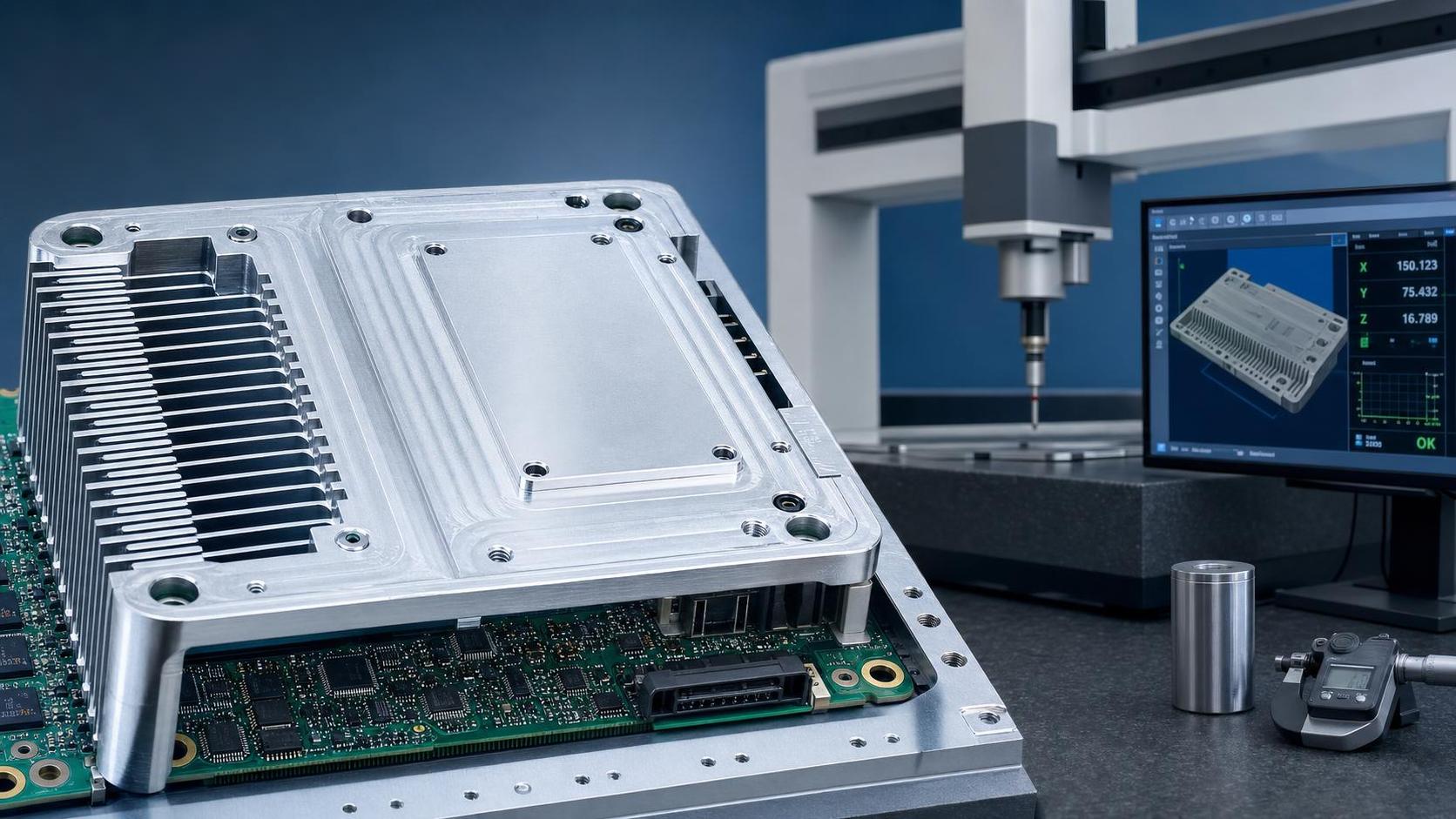
- Confirm the inspection method. A CMM, surface plate method, or other traceable metrology approach is more useful than a verbal assurance.
- Ask if the measured surface remains stable after anodizing, plating, or secondary drilling. Distortion can appear late in the route.
- Review handling and packaging. A precisely milled face that gets dinged in transit is still a nonconforming interface.
A common mistake is treating flatness and parallelism as interchangeable. They are not. A heat sink base may be parallel to a reference face and still contain local waviness that reduces real contact area. For thermal applications, local surface condition matters more than many purchasing checklists admit.
Surface finish is not cosmetic
Technical evaluators often receive a drawing with a roughness callout but no discussion of why it exists. The reason is straightforward: surface finish changes how well the heat sink couples with thermal interface materials and how consistently clamp force translates into usable thermal contact.
Too rough, and the peaks and valleys may demand more interface material than the stack-up can tolerate. Too smooth, and depending on the interface material and assembly method, you can run into bonding inconsistency or squeeze-out behavior that was not seen in prototype builds. The correct finish is application-specific, so avoid universal rules. What matters is that the finish target matches the actual TIM strategy and is verified after the final machining stage.
If the supplier says the finish is “standard machined,” that is not enough for a qualification decision. Ask for the roughness parameter being controlled, the measurement method, and where on the surface it is sampled. Without that, comparisons across vendors are weak.
Look closely at hole position and datum discipline
A heat sink can lose performance even when the base itself is good. Mislocated holes, off-axis tapped features, and poor datum transfer during industrial milling can shift clamp force away from the intended pressure map. On a PCB assembly, that can tilt the sink, bow the board, or create uneven compression over the package.
This matters even more on assemblies built near the mechanical limits of BGAs, large power packages, or insulated metal substrate sections. The thermal team may model ideal, centered loading. Production hardware rarely behaves that cleanly unless the machined features are controlled from the same functional datum structure used by the assembly fixture.
Good review questions here are simple and revealing:
- Which datums are used for base machining, hole creation, and final inspection?
- Are the mounting features machined in one setup or repositioned across operations?
- Does the supplier track positional capability on the actual production machine, or only on first article samples?
- How is burr formation controlled around holes and slots that sit near the board or insulating layer?
Burr control is worth separating out. A tiny raised edge can interfere with seating, scratch coatings, or create an assembly offset that is hard to spot visually but obvious in thermal resistance drift.
Do not ignore edge geometry and local features
Small pockets, relief cuts, slots for keep-out zones, and milled channels for nearby components are common in dense PCB thermal packaging. These local features are exactly where tolerance problems hide. A shallow pocket that goes slightly deep may reduce stiffness. A relief that shifts laterally may contact a tall component or reduce creepage distance. A thin fin root can become a vibration or fatigue concern if the machining route leaves stress risers.
This is also the point where design intent and manufacturing language often drift apart. Engineering may think a cutout is just for clearance. The machinist may see it as a standard pocket. For technical assessment, review the local feature stack against the actual PCB assembly drawing, not just the standalone heat sink print.
Material is only half the story
It is easy to over-focus on whether the heat sink is aluminum, copper, or a hybrid assembly. Material conductivity matters, but poor industrial milling can erase a surprising amount of that advantage by degrading interface quality. A higher-conductivity material with poor contact can underperform a lower-conductivity part that sits flat, loads evenly, and maintains stable bond-line thickness.
For evaluators, this means material certificates should be reviewed alongside machining capability, not ahead of it. The right question is not just “what alloy is used?” but “can this supplier machine and hold the functional geometry this alloy requires without distortion, chatter, or post-process movement?”
If a supplier proposes a material substitution, re-check the milling route. Different machinability can change surface integrity and feature consistency even when the nominal design stays unchanged.
Qualification should include assembly reality
Bench measurements on loose parts are not enough. The right evaluation happens in assembled condition, with the actual fasteners, torque values, interface material, PCB support condition, and expected thermal cycling profile. This is where marginal machining tolerance starts to show up.
Some teams discover late that a heat sink passes dimensional inspection but creates board flex outside comfort range during screw-down. Others see acceptable initial temperatures, then rising thermal resistance after cycling because the contact pattern was never robust. Those are not purely thermal failures. They are tolerance stack failures expressing themselves thermally.
Where formal reliability thresholds are involved, tie the review back to your actual compliance framework. SCM’s audience will already be familiar with standards-based qualification thinking, so this is where IPC-Class 3 build expectations and ISO 9001 process discipline become relevant as part of supplier confidence, not as substitutes for application-specific validation. Neither standard alone confirms heat sink performance; they only strengthen the process foundation around it.
What to ask before approving a supplier
- Show the control plan for the functional mating surface, including metrology and sampling frequency.
- Provide first article data that includes flatness, roughness, and positional accuracy on critical mounting features.
- Clarify whether secondary operations can change the contact face and how that risk is checked.
- State how burrs, edge break, and cleaning are controlled before shipment.
- Confirm that incoming lots remain traceable to machine, setup, and inspection records.
- Run at least one assembled validation build using production-intent torque, TIM, and board constraints.
If any of those answers come back vague, qualification is not finished. It just means the thermal risk has not been measured yet.
For technical evaluators, the practical takeaway is simple: treat industrial milling as part of the thermal system, not as a background fabrication step. Heat sink performance on a PCB is built from contact quality, feature accuracy, assembly loading, and process repeatability working together. Review those items directly, ask for evidence instead of generic precision claims, and validate in the assembled state where real failures appear.
Recommended News
- Heat DissipationHow to prevent overheating in automotive PCB power distributionPrevent overheating in automotive PCB power distribution with practical tips on copper layout, thermal paths, and testing. Discover how to reduce hotspots and improve reliability.
- Heat DissipationCan heat spreading intelligence identify hot spots in PCB designs?Discover how heat spreading intelligence identifies PCB hot spots before fabrication. Learn to assess thermal models, validate predictions, and choose design changes that improve reliability.
- Heat DissipationWhich heat sink materials suit high-power electronics made in Germany?Heat sink materials Germany: compare aluminum, copper, graphite, and hybrid designs for high-power electronics. Find the right balance of thermal performance, weight, cost, and manufacturability.
- Heat DissipationHow to assess a graphite materials supplier's capability for thermal partsGraphite materials supplier assessment starts with more than machining. Discover how to evaluate thermal performance, purity, precision, cleanliness, traceability, and testing for reliable thermal parts.
- Heat DissipationHow to assess a heat dissipation supplier before placing an orderHeat dissipation supplier assessment guide: verify thermal performance, materials, process control, samples, capacity, and total risk before placing an order.
- Heat DissipationHow automotive PCB material selection affects thermal reliabilityAutomotive PCB material selection shapes thermal reliability. Explore CTE, Tg, moisture resistance, stack-up design, and proven qualification strategies for demanding vehicle electronics.