
What Standard Tests Measure Relay Contact Resistance Degradation?
DETAILS
What Standard Tests Measure Relay Contact Resistance Degradation?
Yes. There are standard test methods for relay contact resistance degradation, but there is no single test that can predict every field failure. Relay contacts degrade through a combination of electrical switching stress, surface film growth, mechanical wear, vibration, humidity, temperature cycling, and sometimes contamination introduced during assembly. A useful qualification plan therefore measures contact resistance repeatedly while exposing the relay to the stresses it will actually see in service.
For engineers, the practical question is rarely just “Does the relay meet its initial contact-resistance specification?” A new relay can measure very well on a bench and still become unreliable after thousands of low-level signal operations, hot-load switching cycles, or exposure to corrosive humidity. Procurement teams face a related problem: two suppliers may state the same nominal contact resistance, yet their test current, load profile, failure criteria, and measurement timing may be completely different.
That is why standardized relay testing should be read as a framework, not a checkbox. The relevant standards define how tests are conducted, while the application determines which stresses deserve the most attention.
The standards most often used for relay contact evaluation
For electromechanical relays, the IEC 61810 family is one of the central reference points. IEC 61810-1 addresses general and safety requirements for elementary relays, while other parts of the series cover reliability, test procedures, terminology, and related product categories. Relay manufacturers commonly use this framework when defining electrical endurance, mechanical endurance, insulation, operate/release characteristics, and contact performance requirements.
The exact applicable document depends on relay type and market. Signal relays, power relays, automotive relays, safety relays, reed relays, and aerospace-qualified relays may be assessed under different product specifications. In military and aerospace supply chains, relevant component specifications and test methods may also refer to documents such as MIL-STD-202, including contact-resistance measurement methods where applicable. For connector-style contact measurement techniques, IEC 60512 and EIA-364 methods are often useful technical references, particularly for four-wire resistance measurement, although a connector test method should not be treated as a complete relay endurance qualification.
Environmental testing is often selected from broader component standards. IEC 60068 is widely used for temperature, humidity, vibration, shock, and related environmental test conditions. Automotive programs may additionally impose vehicle-specific electrical and environmental requirements. The important point is that a relay contact resistance result only has meaning when the associated load, operating cycles, environment, and measurement method are visible.
Contact resistance is not measured the same way in every relay test
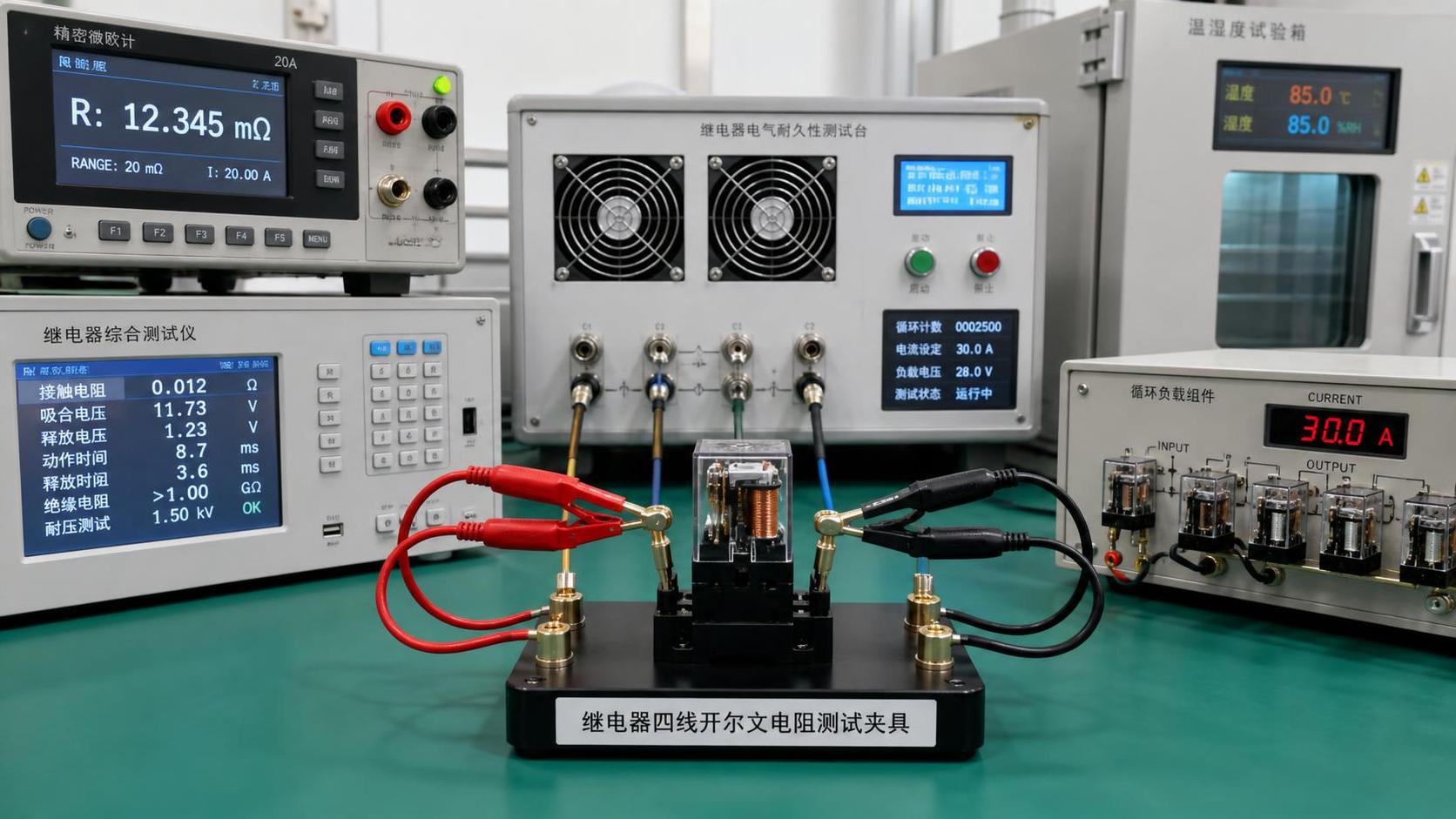
A contact resistance measurement is usually derived from voltage drop across a closed contact at a defined test current. For low resistance values, a four-wire Kelvin method is generally preferred because it reduces the influence of lead and fixture resistance. This sounds straightforward, but the selected current can change what the test detects.
A higher measurement current may break through a thin oxide or sulfide film and make a marginal low-level contact appear healthy. A dry-circuit or low-level measurement, by contrast, is intended to avoid electrically disturbing the contact surface. It is more sensitive to films, light contamination, and insufficient contact force. This distinction matters in alarm loops, instrumentation, telecom equipment, medical electronics, and low-voltage sensing circuits. A relay that performs satisfactorily at an ampere-level load may still be unsuitable for microampere or millivolt-level switching.
For that reason, a supplier data sheet should be checked for more than the headline value. Ask how the resistance was measured: test current, open-circuit voltage, measurement timing, number of samples, contact configuration, and whether the reading was taken before or after environmental recovery. “Maximum contact resistance” without those conditions is not a complete reliability statement.
One common mistake is comparing a milliohm reading taken under a relatively robust current with a dry-circuit requirement from a sensitive signal application. They are not interchangeable. Another is treating a final static resistance reading as proof that no intermittent interruption occurred during vibration or switching. A relay can pass a post-test resistance check and still produce brief discontinuities that matter to a control system or communication link.
Electrical endurance testing is usually the decisive test
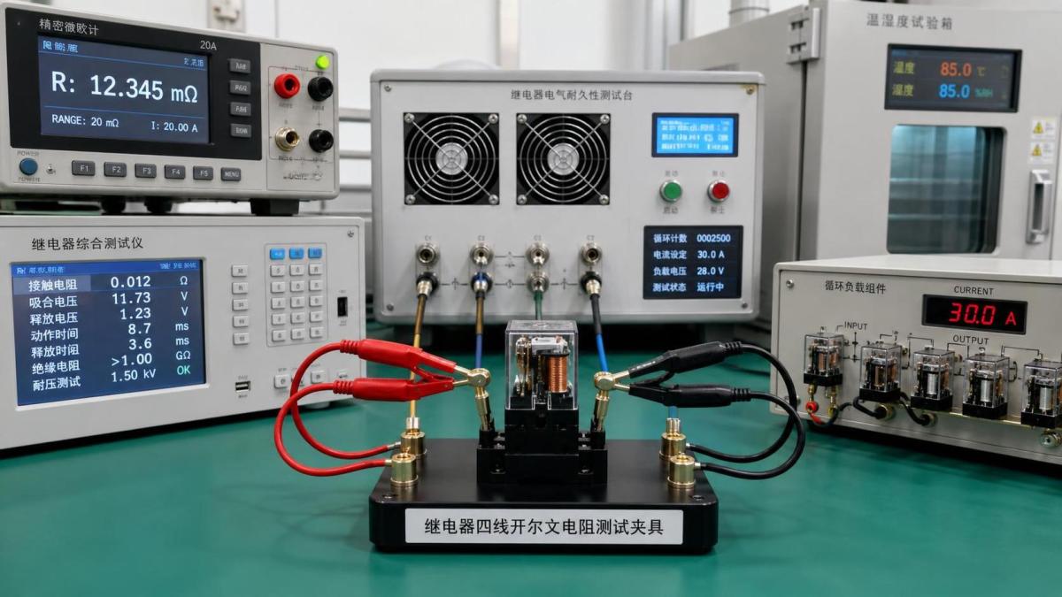
Electrical endurance testing cycles the relay while it makes and breaks a specified load. The load can be resistive, inductive, capacitive, lamp-like, motor-related, or a defined DC switching condition. The difference is not cosmetic. A relay rated for a resistive load can experience substantially greater contact stress when opening an inductive DC circuit, because the stored energy encourages arcing. Capacitive inrush can create a different failure mechanism: contact pitting, welding, or transfer material caused by high peak current at closure.
During an endurance program, contact resistance is commonly checked at predetermined intervals and at the end of the test. The test may also monitor failures to close, failures to open, welded contacts, excessive operate or release time, and unacceptable temperature rise. The contact resistance trend is often more informative than a single final value. A gradual upward drift can point to wear or film formation; abrupt jumps may suggest material transfer, mechanical instability, or a damaged contact surface.
The load profile must resemble the design reality. Testing a relay at its nominal AC resistive rating does not validate a 24 VDC inductive solenoid application. Likewise, a relay switching a low-energy logic signal should not be qualified only with a load that provides enough wetting current to clean the contacts each time. The right test is sometimes inconvenient, but it is less expensive than explaining intermittent field failures after volume deployment.
Environmental tests expose failure modes that cycle counts miss
Electrical endurance alone does not cover the real life of many relays. In outdoor equipment, industrial cabinets, transportation electronics, and factory-floor control systems, the contact surface may be affected by humidity, condensation, sulfur-containing gases, dust, flux residues, or temperature excursions. A relay can remain mechanically functional while its contact interface becomes less reliable.
Temperature cycling is useful for identifying stresses from dissimilar materials, changes in spring force, package cracking, and solder-joint issues around the relay. Damp heat testing can reveal corrosion susceptibility and insulation deterioration. Vibration and mechanical shock testing are particularly relevant where relays sit near motors, pumps, compressors, road vibration, or moving machinery. In these cases, continuity monitoring during the applied stress may be more valuable than measuring resistance only after the event.
There is also a sequencing question. Some programs perform environmental exposure first and then run electrical endurance; others alternate stresses or measure after each stage. Neither arrangement is universally superior. If the concern is corrosion-induced film growth, measuring immediately after exposure and again after a defined recovery period may show different behavior. If the concern is whether vibration causes operational interruption, real-time monitoring is the better fit.
How to interpret “degradation” rather than just pass/fail
Contact resistance degradation does not always mean a smooth increase from a few milliohms to a larger value. Relay contacts can be erratic. Surface films may cause unstable readings. Contact bounce can create transient voltage disturbances. Material transfer after repeated arcing can leave a contact pair with uneven topography, producing a result that varies according to closure position and force.
A technically useful test report should therefore document more than the final average. It should identify the measurement circuit, sample condition, load type, operation rate, number of cycles completed, environmental condition, applicable acceptance limit, and observed failures. Where feasible, retaining individual-unit data is better than reporting only a group mean. Averages can hide a small number of unstable relays, and those outliers are often what a field return population looks like at an early stage.
Engineers should also distinguish between contact resistance and total path resistance. PCB traces, solder joints, terminals, crimp interfaces, and test fixtures can add resistance to the measurement. In a tightly specified system, especially where micro-tolerances and thermal margins are already constrained, poor fixture design can create misleading results. Kelvin probing as close to the relay terminals as practical reduces that risk.
A practical qualification approach for sourcing teams
When comparing relay suppliers, start by defining the actual switching duty rather than asking for a generic reliability report. Record the nominal and peak load, AC or DC behavior, inductance or capacitance, operating frequency, ambient conditions, expected life, and whether the circuit is dry or wet. Then request the test standard and the detailed conditions used to support the quoted contact resistance and endurance rating.
For a high-risk application, a reasonable validation package often combines initial low-level resistance measurement, application-representative electrical endurance, post-endurance resistance checks, and the environmental tests most likely to affect the installation. Add vibration continuity monitoring when interruption is safety-critical or system-critical. If a relay is mounted on a dense PCB, assess the assembled board as well; relay behavior can be influenced by soldering profiles, board flexure, contamination control, and nearby heat sources.
This is where independent engineering review has practical value. SiliconCore Metrics examines component reliability alongside PCB fabrication, SMT assembly, active and passive components, and thermal packaging because relay performance does not exist in isolation. A contact test report may look compliant on its own, yet still leave unanswered questions about measurement conditions, manufacturing traceability, or compatibility with an IPC-Class 3 assembly environment. Comparing test methods rather than simply comparing catalog values gives R&D and procurement teams a much clearer basis for supplier selection.
So, are there standard test methods for relay contact resistance degradation? Absolutely. IEC relay standards, environmental test frameworks, and established low-resistance measurement practices provide the foundation. But the test plan should be built around the relay’s real load and environment. If the quoted resistance value does not state how it was measured, or the endurance test does not resemble the intended switching circuit, treat that result as preliminary—not as proof of long-term reliability.
Recommended News
- RelaysHow to vet an industrial automation distributor for genuine relaysVet an industrial automation distributor with confidence. Learn how to verify relay authenticity, traceability, and quality controls to reduce downtime and sourcing risks.
- RelaysWhat Standard Tests Measure Relay Contact Resistance Degradation?Are there standard test methods for relay contact resistance degradation? Explore IEC standards, endurance testing, Kelvin measurement, and environmental validation for reliable relay sourcing.
- RelaysVietnam Tariff Shift Favors China-Origin Relays Until 2027Vietnam tariff shift favors China-origin relays until 2027. Learn how the 3% tax on non-ASEAN relay imports impacts sourcing, costs, and procurement strategy in Vietnam.
- RelaysJapan Enforces JIS C 5012:2026 Relay EMI Test RuleJapan Enforces JIS C 5012:2026 Relay EMI Test Rule: learn how the new 1.8-2.4 GHz radiated immunity and IEC 61000-4-3:2024 report requirements may impact relay compliance, cost, and Japan market access.
- RelaysWhen a Relay Switches Factory Becomes a Risk to Product QualityRelay switches factory risks can quietly damage product quality, safety, and reliability. Learn the warning signs, audit points, and how to choose a stable supplier.
- RelaysHow to Compare Relay Switches Factory Capabilities for Stable SupplyRelay switches factory comparison starts with capacity, quality control, traceability, and lead time stability. Learn how to identify reliable suppliers and reduce sourcing risk.